Technical Art Coordinate Transformation Systems
- Pavel Zosim
- Feb 17, 2025
- 11 min read
Updated: Jan 30
Technical Art Coordinate Transformation Systems Overview
This article examines the technical art coordinate transformation systems utilized in computer graphics.
In the realm of 3D graphics and technical art, a solid grasp of mathematical principles is crucial. This post provides an in-depth analysis of essential topics—from coordinate systems to transformation hierarchies and conventions (right- vs. left-handed)—all of which are vital for rigging, shader scripting, physics simulation, and ensuring cross-software consistency.
1. Core coordinate Systems
A coordinate system maps points in space using axes. In 3D work you typically encounter:
Local Space (Object Space): Coordinates relative to an object’s pivot (used in modeling and animation).
World Space: A global coordinate system where every object’s position is defined via transformation matrices (usually built from translation, rotation, and scaling).
View Space (Camera Space): Coordinates relative to the camera’s position and orientation (derived via the view matrix).
Projection & Screen Space: Steps that map view-space coordinates to clip-space and finally to 2D pixel coordinates via the projection matrix and viewport scaling.
The full journey of a vertex from creation to rendering:
Local → World: world_position = model_matrix * local_position
World → View: view_position = view_matrix * world_position
View → Clip→ Screen: The projection matrix converts view space into clip space followed by a perspective divide and viewport scaling.

Challenges & Solutions: Issues may arise if pivot points or matrix orders are incorrect. For example, an object may appear misaligned if its local transformation isn’t combined properly with its parent’s world matrix. To solve this, use debugging tools (like Houdini or Blender) to inspect each matrix stage and verify the order of multiplication.Coordinate Conventions: Right-Handed vs. Left-Handed Systems
A coordinate system maps points in space using axes. In 2D, you have two axes (typically X and Y); in 3D, you add a Z-axis. Two primary conventions exist: right-handed (RHS) and left-handed (LHS). While the underlying math remains the same, the orientation of the axes affects rotations, transformations, and asset imports.


1.1 Right-Handed Systems [RHS]
Preferred in rigorous mathematical contexts because it adheres to the right-hand rule—a foundational concept in physics. This consistency leads to predictable behavior in computations and simulations. Tools like OpenGL, Houdini, and Blender typically use RHS.
Orientation:
Thumb = X-axis: Typically points forward.
Index Finger = Y-axis: Points upward.
Middle Finger = Z-axis: Points to the right (orthogonal to both X and Y).
Practical Example: Imagine aligning a character: In an RHS, rotating a cube 45° about its Y-axis (using the right-hand rule) will consistently align its front with the positive X direction. In an LHS, the same rotation might require adjustments (often a flip in the Z-axis) to maintain correct asset orientation.
Challenges & Solutions: When transferring assets between systems, normals, texture coordinates, and rotations may become inconsistent. A common issue is “mirroring” of parts or flipped normals. To resolve this, explicitly convert coordinates (and associated rotation matrices) by applying a conversion matrix or by adjusting texture coordinate origins (bottom-left in OpenGL vs. top-left in DirectX). Testing and unit conversions are key to catching these errors early.1.2 Left-Handed Systems (LHS)
Adopted by specific graphics APIs and software (such as DirectX and, by default, some game engines like Unity and Unreal) for historical reasons, ease of integration, or interface design considerations. Although the underlying math remains the same, the axes’ orientation is flipped relative to RHS, and this must be accounted for during asset transfers and rendering.
Frequently used in DirectX, and in some cases (by default) in game engines like Unity and Unreal.
Orientation:
Thumb = X-axis: Typically points forward.
Index Finger = Y-axis: Points upward.
Middle Finger = Z-axis: Points toward the viewer (inward), opposite to the RHS direction.
Shader Tip: In HLSL, you might need to flip texture coordinates manually:
Key Difference Summary:
Feature | Right-Handed | Left-Handed |
|---|---|---|
Z-axis direction | Away from viewer (depth) | Toward viewer (screen) |
Common Use Cases | OpenGL, Houdini, Blender | DirectX, Unity (default) |
Artist Impact | Affects camera orientation, mesh normals, and interoperability between tools. Asset export/import may require axis flipping. | Requires adjustments during asset transfers, especially for normals and texture coordinates |
1.3 World vs. Local Coordinates
Local coordinates define positions relative to an object’s own pivot. These are later transformed into world coordinates using the parent’s transformation matrix. The relationship is often expressed as: World_Matrix = Parent_World_Matrix × Local_Transform_Matrix
This ensures that—even if an object is far from the world origin—its final world position is correctly computed from its local transform combined with that of its parent.

Note: All these transformations are performed at the program level by the graphics engine using matrix multiplication.
Houdini/Blender: Allow you to inspect both local and world transformations, making it easier to debug issues.
Unity/Unreal: Typically handle these transformations in the engine core, making the multiplication order critical.
Practical Example: For instance, if a character is placed at (1000, 0, 0) in world space and its sword has a local offset of (1, 0, 0), the sword’s final world position becomes approximately (1001, 0, 0) after transformation.
Challenges & Solutions: Errors such as misaligned animations can occur if pivot points are misconfigured or if parent–child relationships are incorrect. The solution is to double-check the transformation hierarchy and verify that local transforms are being multiplied in the proper order.2. Matrix Transformation Order (ROT, SCALE, POS)
The order in which transformations are applied is critical; the same operations in a different sequence can yield completely different results.
Transforming objects in 3D space involves applying rotation (ROT), scaling (SCALE), and position (POS) matrices. The order of these operations is critical, as different sequences yield different results.
Final_Matrix = Translation × Rotation × Scale This order means that scaling occurs first, then rotation is applied, and finally the object is translated. Note that some engines (like Unity) might internally follow a different order (e.g., Scale → Rotate → Translate), so be sure to check documentation.
ROT × SCALE ≠ SCALE × ROT — rotating a scaled object distorts its orientation.
In RHS, a positive rotation around the Z-axis is clockwise, while in LHS, it’s counterclockwise.


Scaling an object and then rotating it produces a different outcome than rotating before scaling.
Practical Example: Scaling an object and then rotating it produces a different outcome than rotating before scaling. In many engines:
Unity: Often applies Scale, then Rotate, then Translate for the local transformation matrix.
Unreal Engine: Uses a similar order but may represent rotations internally with quaternions, affecting interpretation.
3D Modeling Software (e.g., Houdini, Blender):
These applications often allow users to inspect and adjust the local transformation order.
They may also offer options for customizing the transformation hierarchy, affecting the final orientation and position in world space.
This order ensures the object is first scaled, then rotated, and finally moved into position.
Challenges & Solutions: A common problem is an unexpected distortion or misorientation. Debugging can include printing out intermediate matrices or using visualization tools to step through the transformation pipeline and confirm that the applied order matches the intended design.3. Matrices and Coordinate Systems
Matrices are the workhorses of 3D transformations.They convert vertex positions between different coordinate spaces (object, world, view, clip) by encoding translation, rotation, and scaling. Understanding their structure and multiplication rules is essential for shader writing, rigging, and asset integration.
Unity Transformation Matrices
Unity provides several built-in matrices for spatial transformations:
UNITY_MATRIX_MVP
UNITY_MATRIX_MV
UNITY_MATRIX_V
UNITY_MATRIX_P
UNITY_MATRIX_VP
UNITY_MATRIX_T_MV
UNITY_MATRIX_IT_MV
unity_ObjectToWorld
unity_WorldToObject
All of these are 4×4 matrices (four rows × four columns).
Conceptual representation:
UNITY_MATRIX
(
Xx, Yx, Zx, Tx,
Xy, Yy, Zy, Ty,
Xz, Yz, Zz, Tz,
Xt, Yt, Zt, Tw
);
Object-Space and the Model Matrix
In Maya, a polygon object has two nodes: transform and shape.They calculate vertex positions in object-space — relative to the object’s center.
Each vertex is multiplied by the model matrix (UNITY_MATRIX_M).
When the object is moved, rotated, or scaled, the model matrix updates accordingly.
Example: A cube vertex in object-space:([0.5f, -0.5f, -0.5f, 1])
Homogeneous Coordinates (W Channel)
W = 1 → point in space (X, Y, Z, 1)
W = 0 → direction in space (X, Y, Z, 0)
This system allows points and vectors to be handled uniformly in matrix operations.
Matrix Multiplication
Multiplication is valid when columns of the first matrix = rows of the second.
Model matrix (4×4) × Vertex (4×1) → Result (4×1).
This process is applied to all vertices in the vertex shader stage.
Coordinate Spaces
Object-Space → relative to the object’s center.
World-Space → relative to the world’s origin.
Use: unity_ObjectToWorld
View-Space → relative to the camera’s position and orientation.
Use: UNITY_MATRIX_V
Clip-Space (Projection-Space) → relative to the camera’s frustum (near/far clipping planes, field of view).
Use: UNITY_MATRIX_P
Combined Transformations
UNITY_MATRIX_MVP = M × V × P
M → Model
V → View
P → Projection
This matrix transforms vertices from object-space → clip-space, preparing them for rendering on a 2D screen.
Key Shader Function
Unity provides a helper function:UnityObjectToClipPos Used in the vertex shader stage to perform this transformation.
4. The Cross Product
The cross product takes two vectors and produces a third vector perpendicular to both. It is used to compute surface normals and determine rotation axes.

Right-Handed System: (1, 0, 0) × (0, 1, 0) = (0, 0, 1)
Left-Handed System: (1, 0, 0) × (0, 1, 0) = (0, 0, -1)
Practical Example:: In a game, an auto turret might use the cross product to compute the direction perpendicular to a surface, helping it track a target accurately.


If you have a surface defined by two vectors (e.g., local_tangent and local_bitangent), their cross product gives the surface normal. This normal is then transformed into world space using the engine’s normal matrix—critical for proper lighting and shading.
Challenges & Solutions: Incorrect normal calculations can lead to lighting errors or misaligned rotations. Validate your cross product computations in both shader code and transformation matrices. Use debugging tools to ensure the calculated normals match expected results.5. The DOT Product
The dot product takes two vectors and returns a single scalar value. This scalar represents the cosine of the angle between the vectors multiplied by their magnitudes, making it essential for determining how much one vector "points in the direction" of another.

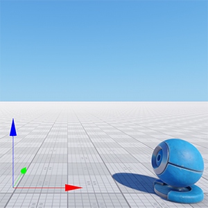
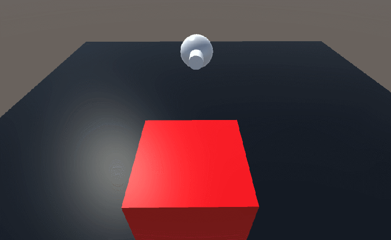
Practical Example:
Consider a boost pad where the red arrow represents speed and the blue arrow represents the pad’s orientation.

The effective boost is calculated as: boost effect = |speed| * |boost| * cos(θ)
where cos(θ) is the result of the dot product.
The dot product allows you to calculate:
Lighting Calculations: Used to compute the intensity of diffuse lighting by taking the dot product between a surface normal and the light direction.
Angle Measurement: Since it yields a cosine value, the dot product helps determine the angle between vectors—useful for backface culling and collision detection.
Challenges & Solutions: Without normalizing vectors, the dot product might yield incorrect values, affecting lighting or boost calculations. Always normalize vectors before computing the dot product. Check for consistency in coordinate systems when transferring assets between tools.6. Quaternions & Euler Angles
Quaternions represent rotation in 3D space using four numbers – 𝑤,𝑥,𝑦,𝑧.
Here, w is the scalar part, and x, y, z form the vector part. Together, they encode information about the rotation angle and axis in a compact form, avoiding problems inherent in describing rotations with successive Euler angles (pitch, yaw, roll).
Euler Angles: Represent rotations via pitch, yaw, and roll but can suffer from gimbal lock—a loss of one degree of freedom.

The rotation axes are not always independent, and solutions are not always unique. It is possible for the plane of two gimbals to align, and a condition known as gimbal lock occurs. In gimbal lock, two of three gimbals are parallel or very nearly parallel, and what began as three degrees of freedom (yaw, pitch, and roll) reduces to two degrees of freedom—two axes of rotation can describe the same rotational motion. At the same time, one degree of freedom is lost and that information disappears. Once gimbal lock occurs, it is impossible to reorient the axes without an external reference.

When using Euler angles, you describe rotation as a series of consecutive rotations around fixed axes (e.g., first around the X-axis (pitch), then the Y-axis (yaw), and finally the Z-axis (roll)).
This approach has two main drawbacks:
The order of rotations matters. Different sequences of rotations can result in different final orientations.
Gimbal Lock. At certain angles, rotation axes can align, resulting in the loss of one degree of freedom.
In contrast, quaternions combine all rotation information into a single entity, preventing gimbal lock and allowing for smooth interpolation between orientations (slerp). This is particularly important in animations and simulations, where stable and predictable rotations are needed.
What do w, x, y, z mean?
For a rotation angle θ around a normalized axis (uₓ, u_y, u_z), the quaternion is defined as follows:
w = cos(θ/2)
x = uₓ · sin(θ/2)
y = u_y · sin(θ/2)
z = u_z · sin(θ/2)
Here:
w – the scalar part, defining the "scale" of the rotation via the cosine of half the rotation angle.
x, y, z – the components of the vector part, defining the rotation axis, multiplied by the sine of half the rotation angle.

Quaternions: A quaternion is an ordered set of four real numbers (𝑤,𝑥,𝑦,𝑧),
often written as 𝑤 + 𝑥𝑖 + 𝑦𝑗 + 𝑧𝑘, where 𝑖,𝑗,𝑘 are not variables but basis elements for 3D space. Quaternions are crucial in 3D graphics because:
They represent rotations in 3D—analogous to how multiplying complex numbers can represent rotations in 2D.
They avoid gimbal lock, a problem where one rotational axis can become “lost” when using Euler angles (pitch, yaw, roll).
They allow for smooth interpolation (slerp) between orientations, which is vital for animations and camera movements.
Key Mathematical Properties
Defining property:
Non-commutative multiplication:
The order of multiplication matters, much like matrix multiplication.
Unit Quaternions:
When using quaternions to represent rotations, we typically use unit quaternions, i.e., quaternions normalized to have a magnitude (norm) of 1:
Normalizing after certain operations helps avoid floating-point errors accumulating over time.
Since multiplication is not commutative, I made this function static to avoid confusing left and right multiplication. Also, I normalize the product so that floating point errors don’t accumulate.
Practical Example:
Imagine modeling an airplane's movement. Its position is represented as a point in 3D space, while its orientation (pitch, yaw, roll) is typically defined using Euler angles.

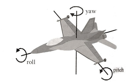
When real pilots talk about their orientation, they talk about roll, yaw, pitch. Pitch is going up or down, yaw is going left or right, roll is, well, roll.
However, as the airplane pitches upward, approaching a vertical position (nose up), a problem arises: when the pitch reaches 90°, the yaw and roll axes align. This leads to gimbal lock, resulting in the loss of one degree of freedom.
Consequences of gimbal lock:
Instead of rotating freely in three dimensions, rotation is constrained to just two.
Roll starts behaving like yaw, causing unpredictable behavior.
By using quaternions, this issue is avoided. Quaternions encode rotation without breaking orientation, ensuring stable and correct movement regardless of angles.
The problem becomes more and more severe when the pitch of the plane becomes higher and higher. The worst case is when the airplane is pointing straight up: then roll and yaw become the same thing! This is called gimbal lock: we have lost a degree of freedom and we can only rotate in 2 dimensions. As long as we use Euler Angles, there is one direction where if we turn too far.
Below is an implementation of a Quat class for working with quaternions:
Challenge 1: Gimbal Lock in Euler Angles
Euler angles define rotations through sequential rotations around fixed axes (pitch, yaw, roll). However, at certain orientations (e.g., when pitch = ±90°), two axes align, leading to **gimbal lock**, where one degree of freedom is lost.

Solution: Use quaternions instead of Euler angles. Quaternions store rotation as a single entity, avoiding gimbal lock and ensuring smooth interpolation (slerp).

Challenge 2: Order-Dependent Rotations
The final orientation of an object depends on the order of Euler rotations, which can lead to unintended results.

Solution: Quaternions apply rotation as a whole transformation rather than step-by-step rotations, ensuring consistent behavior.

Challenge 3: Interpolation Issues
Interpolating between Euler angles (e.g., using linear interpolation) can cause abrupt motion, flipping, or unexpected paths.

Solution: Use spherical linear interpolation (slerp) with quaternions for smooth and natural rotation transitions.

Challenge 4: Converting Between Systems
Switching between Euler angles and quaternions requires careful attention to coordinate system conventions to ensure consistency across different tools (e.g., Unity, Houdini, Unreal).

Solution: Always verify axis orientations and ensure correct conversion formulas when transferring rotations between different software.
References:
Dot Product:
Matrix Decomposition in Unity:
Cross Product:
Quaternions & Euler Angles:
Like this post? ( ´◔ ω◔`) ノシ
Support: Buy Me a Coffee | Patreon | GitHub | Gumroad | YouTube