- Mar 3, 2025
- 9 min read
Updated: Jan 30
TECHNICAL ART COMPUTE SHADERS IN UNITY OVERVIEW
This article introduces technical art compute shaders in Unity and explains how they are used for GPU-based parallel computation.
Compute Shaders are specialized tools that enable massively parallel computations on the GPU, bypassing the traditional rendering pipeline. They’re ideal for tasks like real-time texture generation, physics simulations, and complex data processing.
By leveraging the GPU’s architecture, compute shaders can accelerate tasks that would bottleneck a CPU, making them indispensable for performance-critical applications in Unity.
WHY USE TECHNICAL ART COMPUTE SHADERS IN UNITY?
Important factor when choosing render pipeline is the shaders. Generally, in both High Definition RP and Universal RP, the shaders are created in Shader Graph—a package that provides a node-based interface to create shaders. While this approach allows us to create shaders visually without writing HLSL code, it has its drawbacks. For example, if you upgrade your Unity version (e.g., from 2019 to 2020), your Shader Graph shaders might stop compiling due to version differences, as Shader Graph updates independently of Unity itself.
The best way to create robust shaders in Unity is by writing them in HLSL. This ensures that your shaders will compile correctly across different rendering pipelines and remain stable regardless of Unity upgrades. Furthermore, a major advantage of using HLSL is that it is also supported by Unreal Engine. Since Unreal’s shading language is based on HLSL (especially on DirectX platforms), writing shaders in HLSL allows for easier cross-engine porting and consistency in multi-engine projects.
Parallel Processing: Execute thousands of threads simultaneously.
Performance Gains: Offload heavy math/logic from the CPU.
Versatility: Perfect for non-rendering tasks like physics, AI, or image manipulation.
Key Applications in Unity
Procedural Texture Generation: Create dynamic textures (e.g., noise, fractals) at runtime.
Image Processing: Apply filters or transformations to render textures.
Physics Simulations: Simulate particles, fluids, cloth, or other complex systems.
Advanced Visual Effects: Generate effects such as procedural fire, water, and more.
Data Processing: Execute heavy mathematical operations like matrix multiplications or optimization algorithms.
How Compute Shaders Work
Compute shaders run on the GPU independently of the traditional rendering pipeline.
The structure is built around “kernels” which are functions that execute in parallel over many threads.
Kernel Declaration
Each kernel starts with a #pragma kernel directive followed by the kernel function name (e.g., CSMain).
#pragma kernel CSMain
When you invoke a compute shader via Dispatch, you specify how many groups you want along each axis (X, Y, Z). Each group itself contains a fixed number of threads,
defined by [numthreads(x, y, z)] in the shader.
Total groups = (groupsX × groupsY × groupsZ)
Threads per group = (threadsX × threadsY × threadsZ)
Total threads = (total groups) × (threads per group)
For example, if you dispatch (4, 4, 1) groups and each group has [numthreads(3, 3, 1)], then the total threads are (4 × 4 × 1) × (3 × 3 × 1) = 16 × 9 = 144 threads in total.
Modern GPUs process threads in “warps” or “wavefronts,” typically 32 threads per warp on NVIDIA GPUs or 64 on many AMD GPUs. To maximize efficiency, developers often choose a thread group size (e.g., 64 or 128 threads per group) that aligns with these hardware units. For instance, [numthreads(8, 8, 1)] = 64 threads per group, which can be convenient for certain GPUs.Group-Shared Memory and Synchronization
Shared Memory: Threads within a group can access a fast on-chip shared memory. This is useful for algorithms that require intra-group communication.
Synchronization:
GroupMemoryBarrierWithGroupSync(): Waits for all threads in the current group to finish operations on shared memory.
AllMemoryBarrierWithGroupSync(): Waits for all threads to finish any memory operation (local or global).
Group and Thread IDs
Group ID (SV_GroupID): Identifies the current thread group, which is useful when processing large data sets by blocks.
Thread ID (SV_GroupThreadID or SV_DispatchThreadID): Provides the per-thread coordinate, often mapping directly to pixel coordinates in a texture.
PRACTICING: Procedural Texture Generation - Triangle Sierpinski
Let’s walk through a simple example that generates a procedural texture (e.g., a Sierpinski triangle pattern) using a compute shader and displays it on a GameObject.
Below is a concise explanation of these steps:
Create the C# Script
In Unity’s Project window, right-click and select Create → C# Script.
Name it something like AssignTexture.cs.
Open the script, and inside, add a public field of type ComputeShader.
Attach the Script to a Quad
In the Hierarchy, create a Quad (or any other geometry you want).
Select the Quad and drag the AssignTexture.cs script onto it in the Inspector.
Now the script will run on that Quad when you press Play.
Create the Compute Shader
In the Project window, right-click and select Create → Shader → Compute Shader.
Give it a name (e.g., ComputeShader.compute).
Assign the Compute Shader to the Script
Select the Quad (which has the AssignTexture script).
In the Inspector, locate the Shader field (the public ComputeShader shader).
Drag and drop the newly created .compute file into that field.
C# Script: AssignTexture.cs
Compute Shader Code: ComputeShader.compute
This code declares a kernel called CSMain, uses a thread group size of 8×8×1 (totaling 64 threads per group), and writes a color value into the texture at each pixel position given by id.xy.
Result:

Understanding Thread Groups with Table Examples
When a compute shader is dispatched, the GPU organizes its work in blocks (or groups) of threads. Here, each group is defined with [numthreads(8,8,1)]—meaning each group covers an 8×8 block of pixels. Let’s visualize how threads are arranged within a single group and across groups.
Example 1: Threads in a Single Group (Group ID: 0,0,0) [numthreads(8,8,1)]
Assume that the thread group with ID (0,0,0) covers an 8×8 block. The threads within this group have coordinates (id.x, id.y) ranging from 0 to 7. For clarity, here’s a table showing the mapping of thread coordinates for this group (with id.y starting from 7 at the top down to 0):
7 | (0,7,0) | (1,7,0) | (2,7,0) | (3,7,0) | (4,7,0) | (5,7,0) | (6,7,0) | (7,7,0) |
6 | (0,6,0) | (1,6,0) | (2,6,0) | (3,6,0) | (4,6,0) | (5,6,0) | (6,6,0) | (7,6,0) |
5 | (0,5,0) | (1,5,0) | (2,5,0) | (3,5,0) | (4,5,0) | (5,5,0) | (6,5,0) | (7,5,0) |
4 | (0,4,0) | (1,4,0) | (2,4,0) | (3,4,0) | (4,4,0) | (5,4,0) | (6,4,0) | (7,4,0) |
3 | (0,3,0) | (1,3,0) | (2,3,0) | (3,3,0) | (4,3,0) | (5,3,0) | (6,3,0) | (7,3,0) |
2 | (0,2,0) | (1,2,0) | (2,2,0) | (3,2,0) | (4,2,0) | (5,2,0) | (6,2,0) | (7,2,0) |
1 | (0,1,0) | (1,1,0) | (2,1,0) | (3,1,0) | (4,1,0) | (5,1,0) | (6,1,0) | (7,1,0) |
0 | (0,0,0) | (1,0,0) | (2,0,0) | (3,0,0) | (4,0,0) | (5,0,0) | (6,0,0) | (7,0,0) |
id.y \ id.x | 0 | 1 | 2 | 3 | 4 | 5 | 6 | 7 |
Each cell represents the thread’s unique coordinate within the group, where the third value (0) corresponds to the z-axis.
Example 2: Threads in a Subsequent Group (Group ID: 1,0,0) [numthreads(8,8,1)]
If your texture is larger than one 8×8 block, the shader dispatches multiple groups. For example, consider the group with ID (1,0,0). This group will cover an 8×8 block starting at pixel (8,0) and ending at pixel (15,7):
7 | (8,7,0) | (9,7,0) | (10,7,0) | (11,7,0) | (12,7,0) | (13,7,0) | (14,7,0) | (15,7,0) |
6 | (8,6,0) | (9,6,0) | (10,6,0) | (11,6,0) | (12,6,0) | (13,6,0) | (14,6,0) | (15,6,0) |
5 | (8,5,0) | (9,5,0) | (10,5,0) | (11,5,0) | (12,5,0) | (13,5,0) | (14,5,0) | (15,5,0) |
4 | (8,4,0) | (9,4,0) | (10,4,0) | (11,4,0) | (12,4,0) | (13,4,0) | (14,4,0) | (15,4,0) |
3 | (8,3,0) | (9,3,0) | (10,3,0) | (11,3,0) | (12,3,0) | (13,3,0) | (14,3,0) | (15,3,0) |
2 | (8,2,0) | (9,2,0) | (10,2,0) | (11,2,0) | (12,2,0) | (13,2,0) | (14,2,0) | (15,2,0) |
1 | (8,1,0) | (9,1,0) | (10,1,0) | (11,1,0) | (12,1,0) | (13,1,0) | (14,1,0) | (15,1,0) |
0 | (8,0,0) | (9,0,0) | (10,0,0) | (11,0,0) | (12,0,0) | (13,0,0) | (14,0,0) | (15,0,0) |
id.y \ id.x | 8 | 9 | 10 | 11 | 12 | 13 | 14 | 15 |
Notice how the thread coordinates are offset by 8 in the x-direction compared to the previous group.
Example 3: Threads in a Subsequent Group (Group ID: 0,1,0) [numthreads(8,8,1)]
15 | 0,15,0 | 1,15,0 | 2,15,0 | 3,15,0 | 4,15,0 | 5,15,0 | 6,15,0 | 7,15,0 |
14 | 0,14,0 | 1,14,0 | 2,14,0 | 3,14,0 | 4,14,0 | 5,14,0 | 6,14,0 | 7,14,0 |
13 | 0,13,0 | 1,13,0 | 2,13,0 | 3,13,0 | 4,13,0 | 5,13,0 | 6,13,0 | 7,13,0 |
12 | 0,12,0 | 1,12,0 | 2,12,0 | 3,12,0 | 4,12,0 | 5,12,0 | 6,12,0 | 7,12,0 |
11 | 0,11,0 | 1,11,0 | 2,11,0 | 3,11,0 | 4,11,0 | 5,11,0 | 6,11,0 | 7,11,0 |
10 | 0,10,0 | 1,10,0 | 2,10,0 | 3,10,0 | 4,10,0 | 5,10,0 | 6,10,0 | 7,10,0 |
9 | 0,9,0 | 1,9,0 | 2,9,0 | 3,9,0 | 4,9,0 | 5,9,0 | 6,9,0 | 7,9,0 |
8 | 0,8,0 | 1,8,0 | 2,8,0 | 3,8,0 | 4,8,0 | 5,8,0 | 6,8,0 | 7,8,0 |
id.y \ id.x | 0 | 1 | 2 | 3 | 4 | 5 | 6 | 7 |
Key Points from the Example:
Thread Group Size:
Each group contains 64 threads (8 in x × 8 in y).
Total Threads:
The overall number of threads used is determined by the number of groups dispatched multiplied by 64.
Dispatching Strategy:
To cover a texture with a given texResolution, you calculate the number of groups as:
groupsX = texResolution / workgroup_sizeX
groupsY = texResolution / workgroup_sizeY
For instance, if texResolution is 256 and your workgroup is 16 (using a factor that fits your texture), you may need to dispatch 256 / 16 = 16 groups along both the X and Y axes.
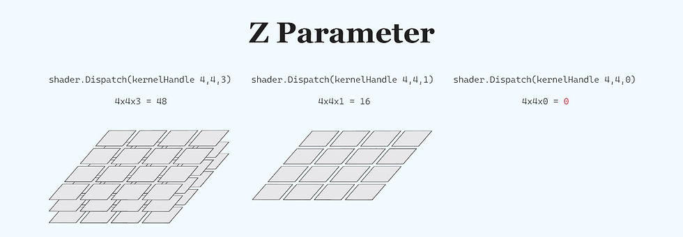
3D Dispatch Requirement:
The Dispatch method requires a non-zero Z value (even if it’s 1) because the threads are defined in three dimensions. Setting Z to 0 means no thread groups are dispatched along that axis.
Example of using:


PRACTICING: Split-Screen Color Effect
We’ll let's split the screen into four colored quadrants using the GPU’s parallel threads by using step() function that will determine whether a pixel belongs to a specific region
The step function in HLSL works as a simple threshold function. It takes two parameters: an edge and a value (x). It returns 1.0 if x is greater than or equal to the edge, and 0.0 otherwise. In other words:
step(edge, x) = (x >= edge) ? 1.0 : 0.0;
This makes it ideal for deciding which region of your texture or screen a pixel falls into. For example, if you want to split the screen into two halves, you can use the half-resolution value as the edge for the x or y coordinate. Pixels with coordinates equal to or above the edge get one value (1.0), and those below get 0.0.
The shift operator (>>) is a bitwise operator that shifts the bits of an integer to the right. Shifting right by 1 bit is equivalent to dividing the integer by 2 (using integer division). For example, if you have a texture resolution of 256, its binary representation
256 = 0b100000000 // "1" followed by 8 zeros
Shifting it right by 1 bit:
256 >> 1 = 0b10000000 // equals 128
This technique is commonly used to quickly compute half of a value (assuming it’s a power of two).

How It Works
int halfRes = texResolution >> 1;
Uses the right shift operator to divide texResolution by 2.
So, if texResolution is 256, halfRes becomes 128.
step(halfRes, id.x) returns 1.0 if the x-coordinate of the current thread (id.x) is greater than or equal to 128; otherwise, it returns 0.0.
Similarly, step(halfRes, id.y) returns 1.0 if the y-coordinate is at least 128, and 0.0 if not.
Example Calculation:
GroupID: (20, 10, 0)
ThreadID (within group): (4, 5, 0)
numthreads: (8, 8, 1)
Then, the DispatchThreadID is calculated as:
DispatchThreadID.x = GroupID.x * 8 + ThreadID.x = 20 * 8 + 4 = 164
DispatchThreadID.y = GroupID.y * 8 + ThreadID.y = 10 * 8 + 5 = 85
DispatchThreadID.z = GroupID.z * 1 + ThreadID.z = 0 * 1 + 0 = 0
So, id = (164, 85, 0).
If halfRes is 128:
step(128, 164) returns 1.0 (because 164 ≥ 128).
step(128, 85) returns 0.0 (because 85 < 128).
Thus, the pixel at (164, 85) is colored red (float4(1, 0, 0, 1)).
This example shows how you can use both the step function and the bit shift operator to quickly compute thresholds and split a texture into regions, which is a common technique in GPU-based procedural effects and multi-screen setups.
Alternative Implementation Using If Statements:
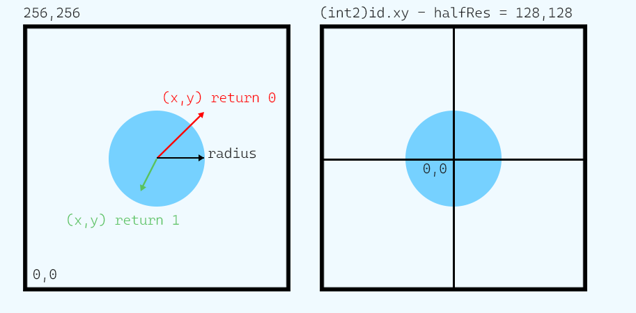
PRACTICING: Drawing a circle Defining center of the screen
In this example, we will draw a circle by determining for each pixel whether it lies within a given radius from the center of the screen. We do this by re-centering the texture coordinates and using the HLSL function length() to calculate the Euclidean distance from the center.

Defining the Circle Center:
The texture’s resolution is provided by the variable texResolution (for example, 256).
We compute halfRes by shifting texResolution right by 1 bit:
int halfRes = texResolution >> 1;
This operation is equivalent to dividing by 2. For instance, if texResolution is 256, then halfRes becomes 128.
By subtracting halfRes from the thread’s coordinate (id.xy), we re-center the coordinate system so that (0,0) corresponds to the center of the texture (instead of the bottom-left corner).
The inCircle Function
We define a helper function, inCircle, that tests whether a point is inside a circle.
It takes a 2D point pt and a radius as parameters, calculates the Euclidean distance from pt using the length() function, and returns 1.0 if the point is inside the circle (i.e., its distance is less than the radius) and 0.0 otherwise.
float inCircle(float2 pt, float radius) {
return (length(pt) < radius) ? 1.0 : 0.0;
}
Here, pt is expected to be given in a coordinate system where the circle’s center is at (0,0).
Determining the Radius
We set the circle’s radius to be one-fourth of the texture resolution.
Using a bit-shift operation, we calculate this as follows:
float radius = (float)(texResolution >> 2);
For a texture with texResolution = 256, shifting right by 2 bits divides by 4, so the radius becomes 64.
Coloring the Pixel
For each pixel (with coordinate id.xy), we subtract halfRes from the coordinate to re-center it. This gives a new coordinate relative to the center of the texture.
Then, we pass this centered coordinate to inCircle along with the computed radius. The result, res, will be 1.0 if the pixel lies within the circle and 0.0 if it does not.
Finally, we set the output color of the pixel using res. In this example, the output color is defined as float4(res, res, 0.0, 1.0), which will display as yellow (red and green combined) for pixels inside the circle and black for those outside.

Detailed Explanation
Centering the Coordinates:By subtracting halfRes from id.xy, the original range (0 to texResolution) is shifted so that the center becomes (0,0). For a 256×256 texture, the coordinates become approximately –128 to +128.
Determining In-Circle:The inCircle function computes the Euclidean distance using length(pt). If the distance is less than the given radius (here, 64), it returns 1.0. Otherwise, it returns 0.0.
Color Output:Using the result from inCircle (stored in res), the pixel’s color is set. Pixels inside the circle get a color value of (1, 1, 0, 1) (yellow), while those outside receive (0, 0, 0, 1) (black). You can easily adjust these values if you want a different color scheme.
Thread Dispatch:With [numthreads(8,8,1)], each thread group processes an 8×8 block of pixels. The overall thread index is calculated by combining the group ID and the thread’s local ID, ensuring that every pixel in the texture is evaluated.
the continuation will be posted below...
Like this post? ( ´◔ ω◔`) ノシ
Support: Buy Me a Coffee | Patreon | GitHub | Gumroad | YouTube


Comments