01 ShaderLab Culling and Depth Testing
To fully grasp culling and depth testing, you must first understand how the Z-Buffer (or Depth Buffer) works. Every pixel rendered on screen has an associated depth value stored in the Z-Buffer. This value determines whether an object appears in front of or behind another. In simple terms, objects are rendered from the closest to the farthest from the camera, which allows the GPU to discard pixels that should remain hidden when geometry overlaps.
Before processing a given pixel, the GPU compares the pixel’s depth against the existing value in the Z-Buffer. If the new pixel is closer than the stored value (or meets the specified comparison criteria), it is drawn and its depth is updated; otherwise, it is discarded.
By manipulating depth-related commands, you can generate various visual effects. Three important ShaderLab commands related to this are Cull, ZWrite, and ZTest.
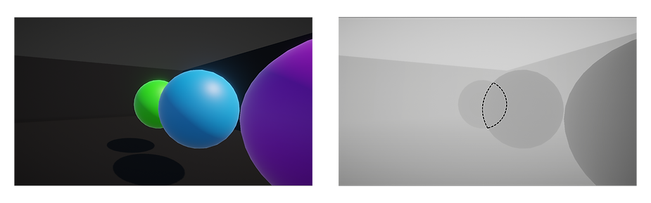 [ Diagram: Hardware Depth Test Comparison Stages ]
Core Concepts
Z-Buffer / Depth Buffer:
A dedicated memory space that holds depth values for each pixel. The closer an object is to the camera, the lower (or sometimes higher, depending on the device) its depth value will be. Each rendered pixel has a depth value representing its distance from the camera. The closer an object is, the lower its depth value. When multiple objects contribute to the same pixel, the one with the lowest depth value (closest to the camera) overwrites the others.
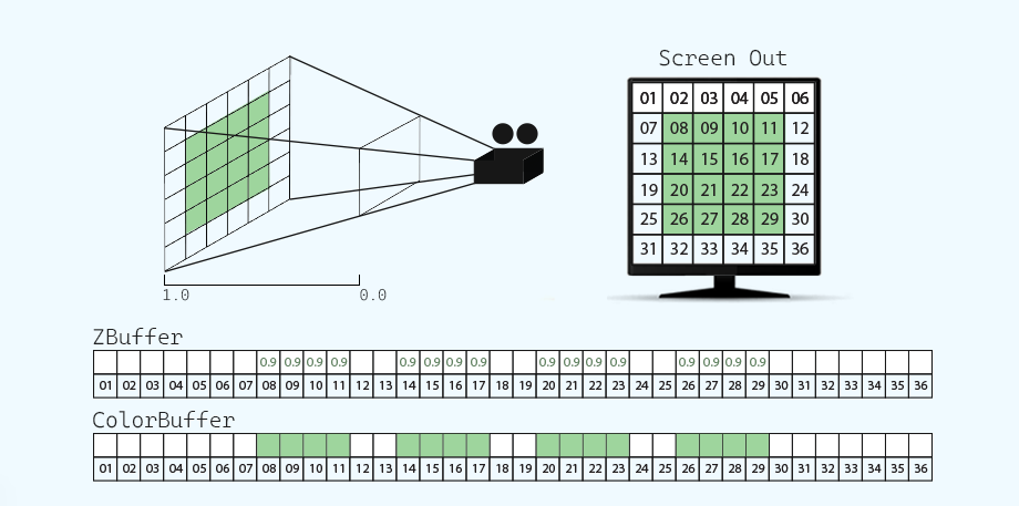 [ Diagram: The Z-Buffer stores the depth of the object in the scene, and the Color Buffer stores the RGBA color information ]
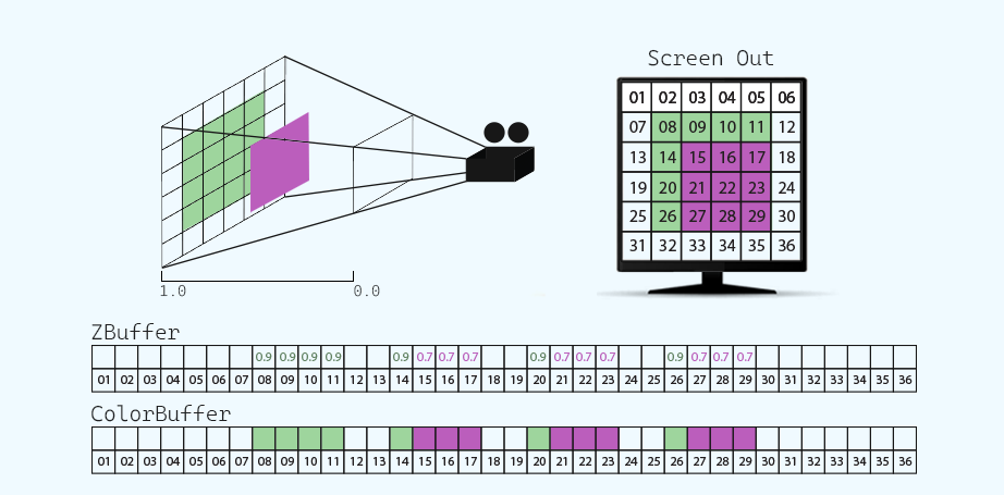 [ Diagram: Depth Testing Conditional Check and Z-Buffer Evaluation ]
- Depth Testing:
A conditional check that determines whether a pixel should be drawn based on its depth value relative to what’s already stored in the Z-Buffer. The most common depth test is "Less" or "LEqual," meaning that only pixels closer (or at the same distance) to the camera will overwrite existing ones. This is the process where the GPU checks each pixel against the Z-Buffer value. If a pixel passes the depth test (for example, if it’s closer than what is already stored), it gets drawn and its depth value is written to the Z-Buffer. - Rendering Order:
For opaque objects, a front-to-back order ensures that only the visible (closest) pixels are processed. For transparent objects, Unity (by default) uses a back-to-front order so that blending occurs correctly.
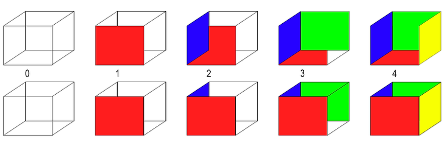 [ Diagram: GPU Sorting Pipeline — Front-to-Back vs. Back-to-Front Layouts ]
Like Tags, culling and depth testing options can be written in different fields: within the SubShader field or the Pass field. The position will depend on the result we want to achieve and the number of passes we want to work with.
Additional Notes on Transparent Shaders and Depth Buffer Management
Transparent shaders introduce additional complexity in depth management due to the blending process. Here are key points and challenges:
- Opaque vs. Transparent Rendering:
Opaque objects are rendered in a front-to-back order, which allows the Z-Buffer to correctly discard hidden pixels. Transparent objects are typically rendered in a back-to-front order (though with Scriptable Render Pipelines, this can be customized) to blend correctly. - Depth Buffer Behavior in Transparent Objects:
Transparent shaders often do not update the Z-Buffer (using ZWrite Off) to prevent artifacts. This is because updating the depth buffer could cause partially overlapped transparent pixels to be incorrectly discarded, leading to issues like parts of an object not being rendered.
For example, consider a cube with a semi-transparent material and two-sided rendering. If the cube is composed of quads (for simplicity), the GPU might render some polygons later even though a closer polygon should have prevented them via ZTest. If depth values were updated, pixels of later-drawn (but farther) polygons might incorrectly overwrite the closer ones. - Sorting Transparent Objects:
When rendering two transparent objects (e.g., with alpha = 0.5), the expected outcome is that the first object blends with the opaque background, and then the second object blends with the updated background. This requires careful management of the Z-Buffer—if updated, artifacts can appear (e.g., parts of one object may vanish behind another).
Practical Solutions: There is no one-size-fits-all fix. Some approaches include:
- Shader Variants: Write separate shader variants that use different ZWrite settings depending on the object's alpha. For instance, one variant with ZWrite On for alpha values in [1.0, 0.5) (to render an "external shell") and another with ZWrite Off for alpha values in [0.5, 0].
- Two Different Shaders: Use two shaders (one with ZWrite On and one with ZWrite Off) and combine their output to handle different transparency levels.
- Custom Render Pipeline Adjustments: With Scriptable Render Pipelines, you can sometimes modify the transparent rendering order (for example, using front-to-back transparent rendering) to better suit your needs.
Example Problem Scenario: Imagine placing one transparent object (e.g., a helmet) inside another (e.g., a wall) so that the helmet appears on both sides of the wall. If ZWrite is enabled (writing depth), half of the helmet might not render because the wall’s depth overrides it. With ZWrite Off, both objects blend correctly, though this may affect overall scene depth sorting.
Shader Graph Consideration: Unfortunately, Shader Graph currently does not offer easy access to change subshader properties like ZWrite directly (unlike some alternatives such as Amplify Shader Editor). In such cases, you may need to create a custom shader (for example, by starting with a Standard Surface Shader and modifying the generated code) to achieve the desired depth behavior.
ShaderLab Cull Mode
Controls which faces of a polygon are rendered (Back, Front, or Off). Works consistently across pipelines; additional HDRP material settings may enhance its usage. In 3D models, each polygon has a front and a back face:
Cull Back(default): Only the front faces are rendered. This is typically more efficient.Cull Front: Only the back faces are rendered.Cull Off: Both faces are rendered. This can be useful when you need to display double-sided materials, such as thin cloth or foliage.
Static Implementation Example:
Shader "Custom/CullExample" {
    Properties { /* ... */ }
    SubShader {
        // Render only the front faces (default behavior)
        Cull Back
        Pass {
            CGPROGRAM
                // Shader code...
            ENDCG
        }
    }
}
Dynamic Implementation via Material Inspector Enum:
Shader "Custom/DynamicCullExample" {
    Properties {
        [Enum(UnityEngine.Rendering.CullMode)] _Cull ("Cull Mode", Float) = 0
    }
    SubShader {
        // Use the value of _Cull for culling
        Cull [_Cull]
        Pass {
            CGPROGRAM
                // Shader code...
            ENDCG
        }
    }
}
Another helpful option occurs through the semantics SV_IsFrontFace, which allows us to project different colors and textures on both mesh faces. To do so, we simply declare a boolean variable and assign such semantics as an argument in the fragment shader stage.
fixed4 frag (v2f i, bool face : SV_IsFrontFace) : SV_Target
{
    fixed4 colFront = tex2D(_FrontTexture, i.uv);
    fixed4 colBack = tex2D(_BackTexture, i.uv);

    return face ? colFront : colBack;
}
ShaderLab ZWrite
ZWrite controls whether a shader writes depth information (i.e., the pixel’s distance to the camera) into the Z-Buffer. This command controls the writing of the surface pixels of an object to the Z-Buffer, that is, it allows us to ignore or respect the depth distance between the camera and an object. This is especially important when dealing with transparency e.g., when we activate the Blending options. Typically On for opaque objects and Off for transparent ones to avoid Z-fighting.
ZWrite On(default): The shader writes depth information. This is typical for opaque materials.ZWrite Off: Depth values are not written. This is usually used for transparent materials to prevent issues like Z-fighting (flickering when objects overlap).
Shader "InspectorPath/shaderName"
{
    Properties { /* ... */ }
    SubShader
    {
        Tags { "Queue"="Transparent" "RenderType"="Transparent" }
        Blend SrcAlpha OneMinusSrcAlpha
        ZWrite Off

        Pass {
            // Shader code here...
        }
    }
}
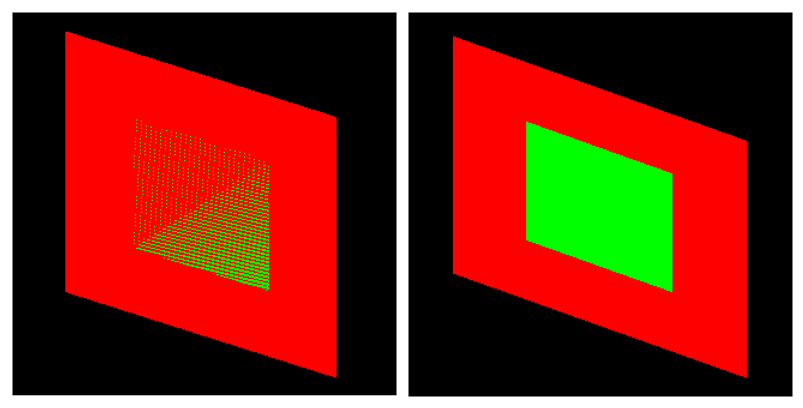
The Z-fighting occurs when we have two or more objects at the same distance from the camera, causing identical values in the Z-Buffer.
This effect occurs when trying to render a pixel at the end of the rendering pipeline. Since the Z-Buffer cannot determine which element is behind the other, it produces flickering lines that change shape depending on the camera’s position. To correct this issue, we simply need to disable the Z-Buffer using the “ZWrite off” command.
 [ Diagram: Planar Co-planar Geometry Conflict Resulting in Z-Fighting Artifacts ]
ShaderLab ZTest
ZTest defines how depth testing is performed by comparing each pixel’s depth to the Z-Buffer. It supports several comparison functions:
Less(<): Draws the pixel if its depth is less than the stored depth.Greater(>): Draws if its depth is greater.LEqual(≤): (Default) Draws if the pixel’s depth is less than or equal to the stored depth.GEqual(≥): Draws if the pixel’s depth is greater than or equal.Equal(==): Draws if the depths are exactly equal.NotEqual(!=): Draws if the depths differ.Always: Ignores depth testing and draws every pixel regardless of depth.
ZTest Less: (<) Draws the objects in front. It ignores objects that are at the same distance or behind the shader object.
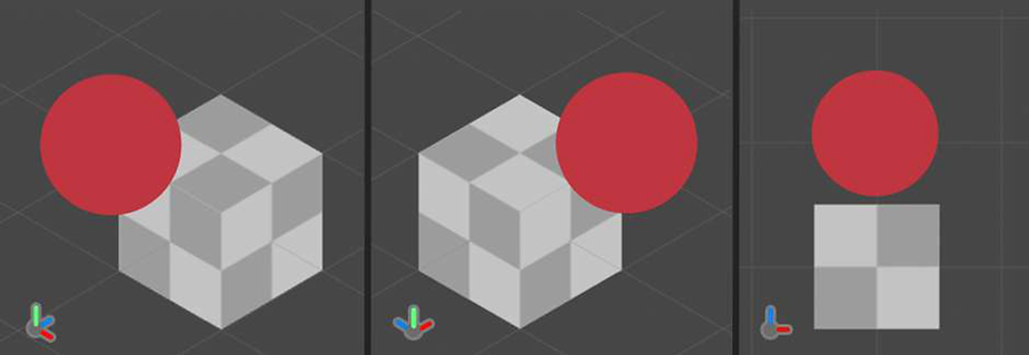
To understand this command, we will do the following exercise: Let’s suppose we have two objects in our scene; a Cube and a Sphere. The Sphere is in front of the Cube relative to the camera, and the pixel depth is as expected.
 [ Diagram: Standard Depth Verification — Sphere Positioned In Front of the Cube Scope ]
If we position the Sphere behind the Cube then again, the depth values will be as expected, why? Because the Z-Buffer is storing depth values for each pixel on the screen. The depth values are calculated concerning the proximity of an object to the camera.
 [ Diagram: Standard Depth Verification — Sphere Occluded by the Cube Volume ]
Now, what would happen if we activated ZTest Always? In this case, Depth Testing would not be done, therefore, all pixels would appear at the same depth on screen.
 [ Diagram: Depth Buffer Evaluation Overridden via ZTest Always Command ]
Example implementation:
Shader "Custom/ZTestExample" {
    Properties { /* ... */ }
    SubShader {
        Tags { "Queue"="Transparent" "RenderType"="Transparent" }
        ZTest LEqual  // Default behavior
        Pass {
            CGPROGRAM
                // Shader code...
            ENDCG
        }
    }
}
ShaderLab Stencil
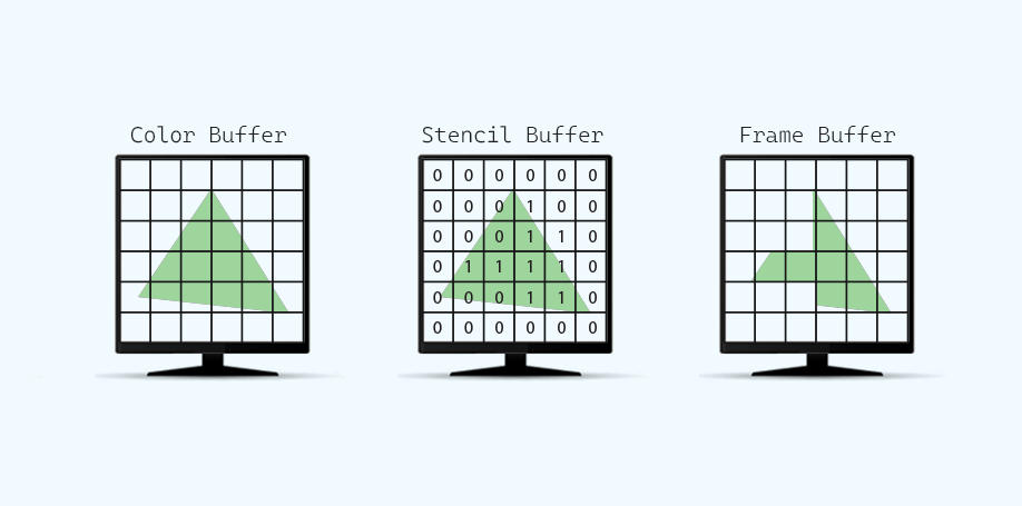
The Stencil Buffer is a specialized buffer that stores an 8-bit integer (values 0–255) for each pixel in the Frame Buffer. Before executing the fragment shader for a pixel, the GPU can perform a Stencil Test — comparing the current value in the Stencil Buffer with a specified reference value. If the test passes, the GPU then performs the depth test; if it fails, the GPU skips further processing for that pixel. Essentially, the Stencil Buffer acts as a mask, letting you control which pixels are drawn and which are discarded.
 [ Diagram: Fragment Rejection Pipeline via Hardware Stencil Evaluation ]
How the Stencil Buffer Works
- Storage: The Stencil Buffer is like a “texture” that covers the entire frame, with each pixel storing an integer between 0 and 255.
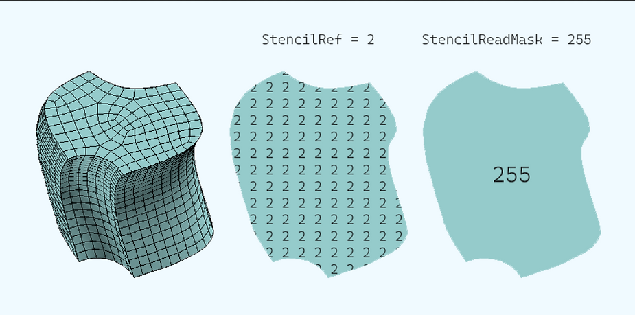
- Stencil Test: Before a fragment is processed, the GPU compares the pixel’s current stencil value (from the buffer) with a reference value that you supply (StencilRef), using a mask (StencilReadMask) and a comparison function (Comp).
The test can be conceptually described as:
if ( (StencilRef & StencilReadMask) [Comp] (StencilBufferValue & StencilReadMask) ) {
    Accept Pixel.
} else {
    Discard Pixel.
}StencilRef: The reference value you want to compare against. Think of it as an ID you write into the Stencil Buffer.StencilReadMask: A mask that determines which bits to consider during the comparison.Comp: A comparison function that evaluates to true or false (see below).
Available Comparison Functions
The following operators can be used for the stencil comparison:
Comp Never: Always fails the test.Comp Less: Passes if the reference is less than the buffer value.Comp Equal: Passes if the values are equal.Comp LEqual: Passes if the reference is less than or equal to the buffer value.Comp Greater: Passes if the reference is greater than the buffer value.Comp NotEqual: Passes if the values are not equal.Comp GEqual: Passes if the reference is greater than or equal to the buffer value.Comp Always: Always passes the test.
 [ Diagram: Matrix of Hardware Stencil Comparison Operations ]
Practical Example
Suppose you have three objects in your scene—a Cube, a Sphere, and a Square—and you want to use the Square as a mask so that only the Sphere inside the Cube is visible.
1. Mask Shader (USB_stencil_ref)
This shader writes a reference value (for example, 2) into the Stencil Buffer for all pixels covered by the mask (the Square). Since we only need to mark the pixels without drawing any color, we disable color output and depth writing.
Shader "Custom/USB_stencil_ref" {
    Properties { /* No visible properties needed */ }
    SubShader {
        Tags { "Queue" = "Geometry-1" }  // Process before default geometry (default Geometry=2000, so here it's 1999)
        ZWrite Off                       // Do not update the depth buffer for the mask
        ColorMask 0                      // Discard color output (make it invisible)
        Stencil {
            Ref 2                        // StencilRef = 2; marks the mask with value 2
            Comp Always                  // Always pass the stencil test, so all pixels covered by the mask get set to 2
            Pass Replace                 // Replace the current stencil value with the reference value
        }
        Pass {
            CGPROGRAM
                // Minimal shader code; even an empty pass is enough since no color is drawn
            ENDCG
        }
    }
    FallBack "Diffuse"
}
2. Masked Object Shader (USB_stencil_value)
This shader renders the object (e.g., the Cube) but only where the Stencil Test indicates it is not part of the mask. It compares the current Stencil Buffer value with the reference value (2) and uses a comparison function to decide whether to draw a pixel.
Shader "Custom/USB_stencil_value" {
    Properties {
        _Color ("Color", Color) = (1, 1, 1, 1)
    }
    SubShader {
        Tags { "Queue" = "Geometry" }
        // Keep ZWrite on so depth is properly updated for this object
        ZWrite On
        Stencil {
            Ref 2                        // Must match the mask's reference value
            Comp NotEqual                // Pass the test only if the stencil value is NOT equal to 2
            Pass Keep                    // Keep the existing stencil buffer value
        }
        Pass {
            CGPROGRAM
                // Your regular shader code to render the object
                #pragma vertex vert
                #pragma fragment frag
                fixed4 _Color;
                struct appdata { float4 vertex : POSITION; };
                struct v2f { float4 pos : SV_POSITION; };
                v2f vert (appdata v) {
                    v2f o;
                    o.pos = UnityObjectToClipPos(v.vertex);
                    return o;
                }
                fixed4 frag (v2f i) : SV_Target {
                    return _Color;
                }
            ENDCG
        }
    }
    FallBack "Diffuse"
}
In this example:
- The mask shader (USB_stencil_ref) writes a stencil value of 2 over the area of the Square.
- The masked object shader (USB_stencil_value) renders only where the stencil value is not equal to 2—hiding the Cube where the mask is applied, allowing the Sphere behind it to be visible.
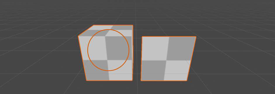 [ Diagram: Stencil Space Exclusion Test Setup — Geometry Queue (Geometry - 1) Execution ]
We configured “Queue” to “Geometry minus one”. Since Geometry defaults to 2000, this equals 1999, processing our mask in the Z-Buffer. Unity processes objects based on their scene position relative to the camera. To disable this, set “ZWrite to Off”. Set “ColorMask to zero” to discard mask pixels in the Frame Buffer, making them transparent.
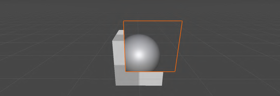 [ Diagram: Frame Buffer Result with ColorMask 0 Masking Enabled ]
02 ShaderLab Pass
A Pass in rendering refers to generating different layers (e.g., color, light, occlusion) separately in 3D software like Maya or Blender. Each Pass renders one object at a time, equivalent to a draw call, so minimizing passes is crucial to avoid significant graphic load.
A Pass in ShaderLab represents a single render pass—a discrete set of rendering instructions executed by the GPU for an object. By default, Unity adds one pass inside the SubShader. However, you can define multiple passes if needed. Each pass is equivalent to one draw call, which means that an object with multiple passes is rendered multiple times. This can be useful for creating layered visual effects (such as separate passes for base color, lighting, and occlusion) but can also significantly increase the rendering workload.
Since each pass equals a draw call, increasing the number of passes can lead to a heavier GPU load. It's best to use the minimum number of passes necessary for your effect.
Below is an example of a simple shader with a single pass, similar to a basic color shader:
Shader "InspectorPath/USB_simple_color" {
    Properties {
        _MainTex ("Texture", 2D) = "white" {}
        _Color ("Color", Color) = (1,1,1,1)
    }
    SubShader {
        Tags { "RenderType"="Opaque" }
        Pass {
            CGPROGRAM
                #pragma vertex vert
                #pragma fragment frag
                // Enable fog support
                #pragma multi_compile_fog
                #include "UnityCG.cginc"

                struct appdata {
                    float4 vertex : POSITION;
                    float2 uv : TEXCOORD0;
                };

                struct v2f {
                    float4 pos : SV_POSITION;
                    float2 uv : TEXCOORD0;
                    UNITY_FOG_COORDS(1)
                };

                sampler2D _MainTex;
                float4 _Color;

                v2f vert (appdata v) {
                    v2f o;
                    o.pos = UnityObjectToClipPos(v.vertex);
                    o.uv = v.uv;
                    UNITY_TRANSFER_FOG(o,o.pos);
                    return o;
                }

                fixed4 frag (v2f i) : SV_Target {
                    fixed4 col = tex2D(_MainTex, i.uv) * _Color;
                    UNITY_APPLY_FOG(i.fogCoord, col);
                    return col;
                }
            ENDCG
        }
    }
    FallBack "Diffuse"
}
If you want to create a shader with two passes (for example, one pass for the base color and another for an additional effect), you would structure your shader like this:
Shader "InspectorPath/DoublePassShader" {
    Properties { /* ... */ }
    SubShader {
        Tags { "RenderType"="Opaque" }
        Pass {
            // First pass: base color
            CGPROGRAM
                // Base shader code here...
            ENDCG
        }
        Pass {
            // Second pass: additional effect (e.g., shine, outline)
            CGPROGRAM
                // Additional effect shader code here...
            ENDCG
        }
    }
}
Render Pipeline Considerations (2024/2025)
- Built-in Render Pipeline: Passes are typically written using
CGPROGRAM/ENDCG. This is the classic method. - URP/HDRP: For Scriptable Render Pipelines, it is recommended to use
HLSLPROGRAM/ENDHLSLinstead. Although the concept of a pass remains the same, the newer syntax provides better compatibility with modern shader targets. Regardless of the pipeline, the idea of each pass representing a separate draw call stays consistent.