01 Coordinate-space pipeline
A 3D point has meaning only inside a coordinate space. During rendering, a vertex moves through a sequence of spaces: from the model's local frame to the world, then to the camera, clip space, and finally the image.
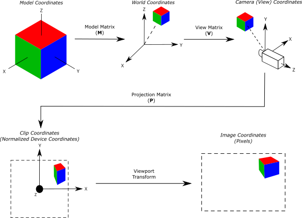
| Space | Relative to | Typical use |
|---|---|---|
| Local / object | The object's pivot and axes | Modeling, rigging, procedural deformation |
| World | The scene origin | Placement, physics, object-to-object queries |
| View / camera | The active camera | Lighting and view-dependent effects |
| Clip / NDC | The camera frustum | Clipping and projection |
| Screen | The viewport or image | Pixels, UI, post-processing |
world = modelMatrix * localPosition
view  = viewMatrix  * world
clip  = projectionMatrix * view
ndc   = clip.xyz / clip.w
Debugging rule: label the space of every position, vector, normal, and matrix. Most transformation bugs begin when two values from different spaces are combined as if they shared one basis.
02 Handedness and interchange
A coordinate system is right-handed or left-handed according to the orientation of its basis vectors. Handedness changes how positive directions, rotations, triangle winding, and cross products are interpreted. The mathematics remains valid in either convention; the danger is an incomplete conversion between them.
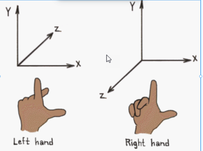
When moving an asset between a DCC, an engine, and a graphics API, verify the complete exchange contract:
- up and forward axes;
- handedness and rotation convention;
- matrix layout and vector multiplication order;
- triangle winding, normals, and tangent-space sign;
- UV origin and texture orientation;
- distance and angle units.
03 Local, world, and hierarchy
Local space makes an object's data independent of scene placement. A child transform is evaluated through its parent hierarchy, so moving a character also moves the prop attached to the character's hand.
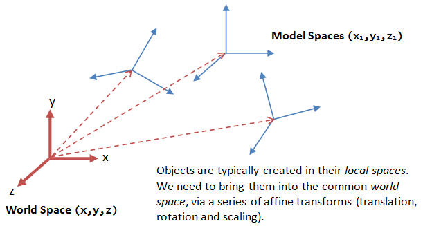
A point uses homogeneous coordinate w = 1, so translation affects it. A direction uses w = 0, so translation is ignored. Normals need special treatment under non-uniform scale: transform them with the inverse-transpose of the relevant linear transform, then normalize.
04 Transformation order
Matrix multiplication is not commutative. Applying scale, rotation, and translation in a different order changes the result—especially when scale is non-uniform or the pivot is away from the origin.
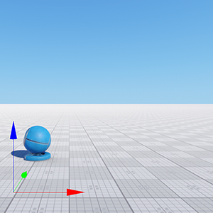
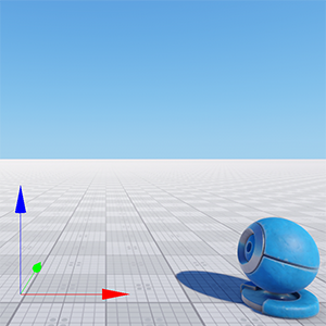
The same transforms composed in different orders produce different positions and orientations.
// Column-vector convention: the rightmost operation runs first.
modelMatrix = translationMatrix * rotationMatrix * scaleMatrix;
worldPosition = modelMatrix * localPosition;
Convention matters: the expression above assumes column vectors. Row-vector systems write the composition in the opposite order. Confirm the convention before copying matrix code between tools or APIs.
05 Dot and cross products
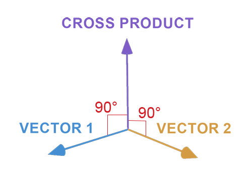
Dot and cross products answer different spatial questions. Both assume that the input vectors are expressed in the same coordinate space.
| Operation | Returns | Technical-art use |
|---|---|---|
| dot(a, b) | A scalar | Angles, facing tests, projection, diffuse lighting |
| cross(a, b) | A perpendicular vector | Normals, tangent frames, side tests, orientation |
06 Euler angles and quaternions
Euler angles are readable and useful for authoring, but they represent a sequence of axis rotations. Their order matters, and certain orientations align two axes, causing gimbal lock and the loss of one effective degree of freedom.


Independent gimbal axes at left; two aligned axes and one lost degree of freedom at right. Animation credit: Mark Hughes.
A unit quaternion stores an orientation as four components. For a normalized axis u = (ux, uy, uz) and rotation angle θ:
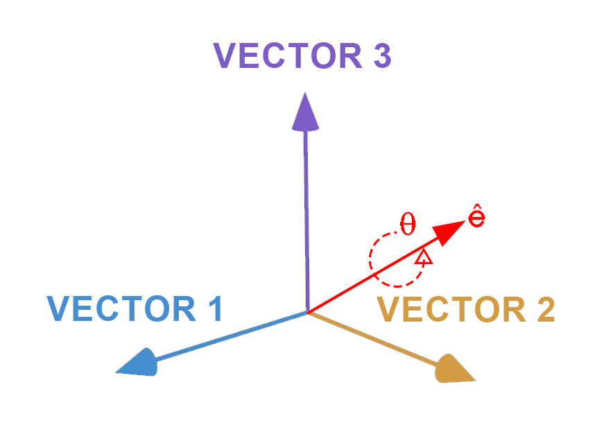
Quaternions avoid the singularity of Euler-angle parameterization and support smooth spherical interpolation. They do not make rotation order commutative: quaternion multiplication still depends on order. Normalize accumulated rotations when numerical drift is possible.
07 Debugging checklist
- Write the source and destination space beside every transformation.
- Test with a point on each positive axis, not only at the origin.
- Visualize basis vectors and normals in the viewport.
- Inspect every parent matrix when a child appears offset.
- Use a non-uniformly scaled test object to expose order and normal errors.
- Verify handedness, units, winding, UV origin, and rotation order at import boundaries.
- Compare intermediate values before debugging the final image.
Practical takeaway: transformations become easier to reason about when space, convention, and multiplication order are treated as part of each value's type—not as undocumented context.
08 References
- [01]COURSE — Dot products.
khanacademy.org/math/multivariable-calculus/dot-products - [02]ARTICLE — Understanding the dot product.
betterexplained.com/articles/vector-calculus-understanding-the-dot-product - [03]ARTICLE — Matrix decomposition in Unity.
pixel.engineer/posts/matrix-decomposition-unity - [04]ARTICLE — The cross product for 3D artists.
andytech.art/the-cross-product-for-3d-artists - [05]ARTICLE — Coding with cross products.
joshcgblog.wordpress.com/coding-with-cross-products - [06]ARTICLE — Understanding quaternions.
allaboutcircuits.com/technical-articles/understanding-quaternions - [07]ARTICLE — Visualizing quaternions with Unity.
luckytoilet.wordpress.com/visualizing-quaternions-with-unity