01 System Philosophy & Dual Workflow
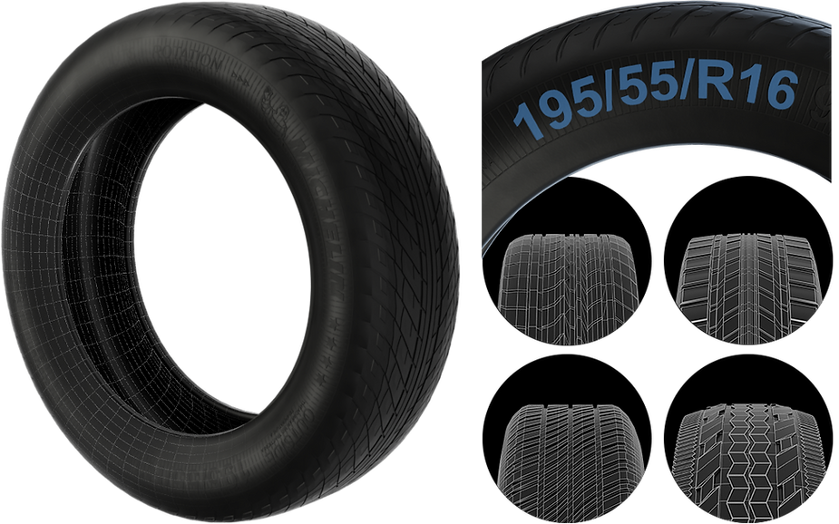
This procedural tire generator is built around real-world automotive dimensions. The focus is not on handcrafted geometry but on procedural logic that remains stable regardless of tread complexity. Instead of modeling the entire tire at once, the system is based on a repeating tread segment distributed procedurally across the surface.
Manual tire modeling does not scale. Variation across different tire sizes is error-prone and labour-intensive. A procedural system reduces rework, enforces consistency, and allows quick preset switching — while keeping the underlying architecture unchanged.
02 Scaling & Physical Consistency
The goal is to generate a flexible and physically accurate tire model based on standard tire measurements. The system accounts for both symmetrical and asymmetrical tread designs.
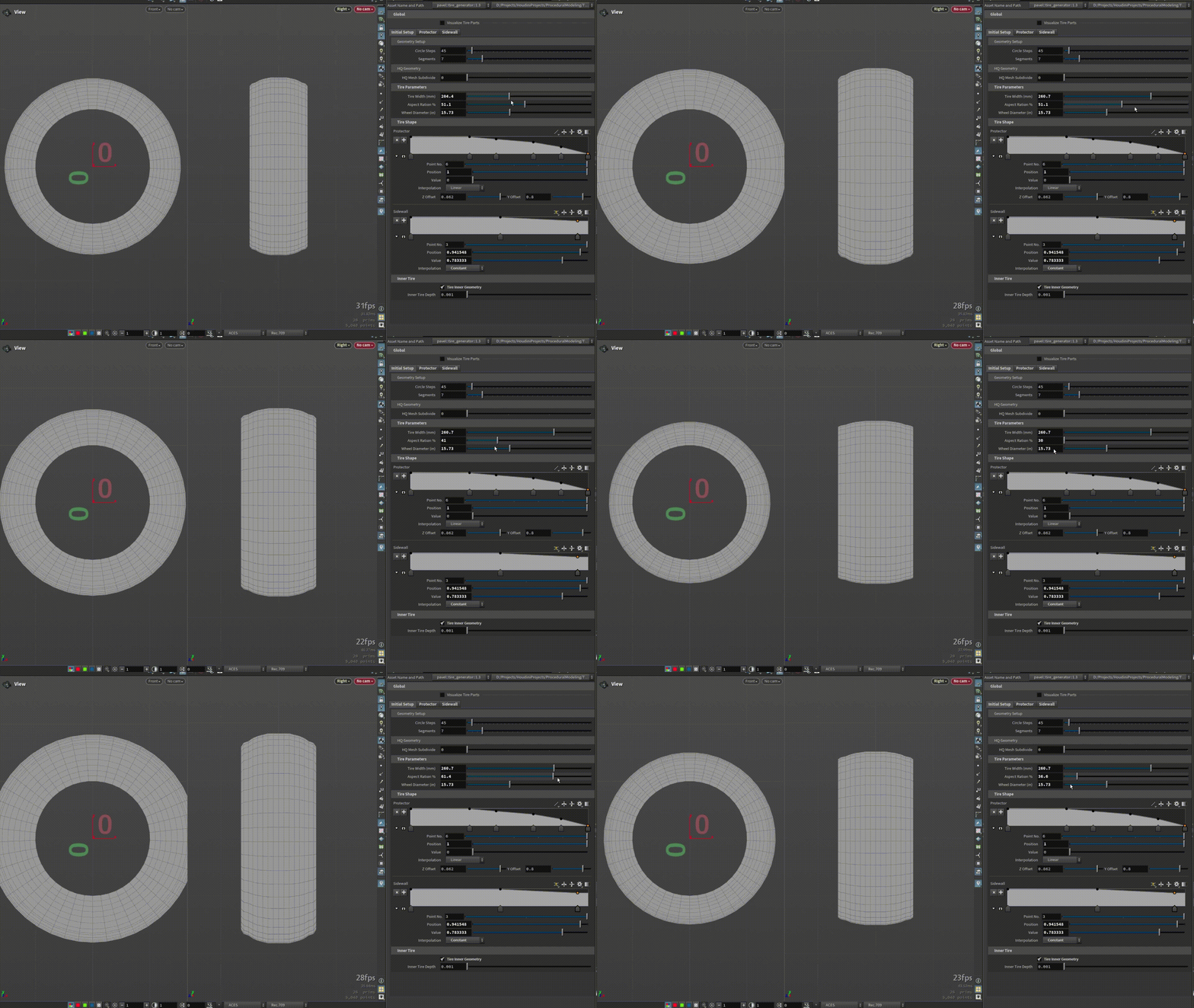
| PARAMETER | UNIT | ROLE IN SYSTEM |
|---|---|---|
| Tire Width | mm | Master scale — controls tread and sidewall surface width |
| Aspect Ratio | % | Drives vertical displacement of the sidewall (sidewall height / width) |
| Wheel Diameter | inches | Dictates the central aperture — inner rim radius |
The internal logic creates a cascading dependency: Tire Width acts as the master scale, Aspect Ratio drives sidewall vertical displacement, and Wheel Diameter defines the rim aperture. All three are converted to meters before any geometry is generated.
VEX Unit Conversion
The core of the system relies on strict unit conversion. Since Houdini operates in meters, normalising diverse input units (mm, inches, %) is critical to maintaining predictable scale across all downstream operations:
// Input parameters — from HDA interface
float tireWidth    = chf('tire_width');          // mm
float aspectRatio  = chf('aspect_ratio') * 0.01; // % to decimal
float wheelDiameter = chf('wheel_diameter');      // inches

// Unit normalisation — all values to meters
f@tireWidth      = tireWidth / 1000;
// sidewall height: convert mm→inches (*0.03937), then scale by aspect,
// then convert inches→meters (/37.37 accounts for circumference factor)
f@sidewallHeight = (tireWidth * 0.03937 * aspectRatio) / 37.37;
f@wheelDiameter  = wheelDiameter / 39.37;
03 Pattern Tiling & Angular Correction
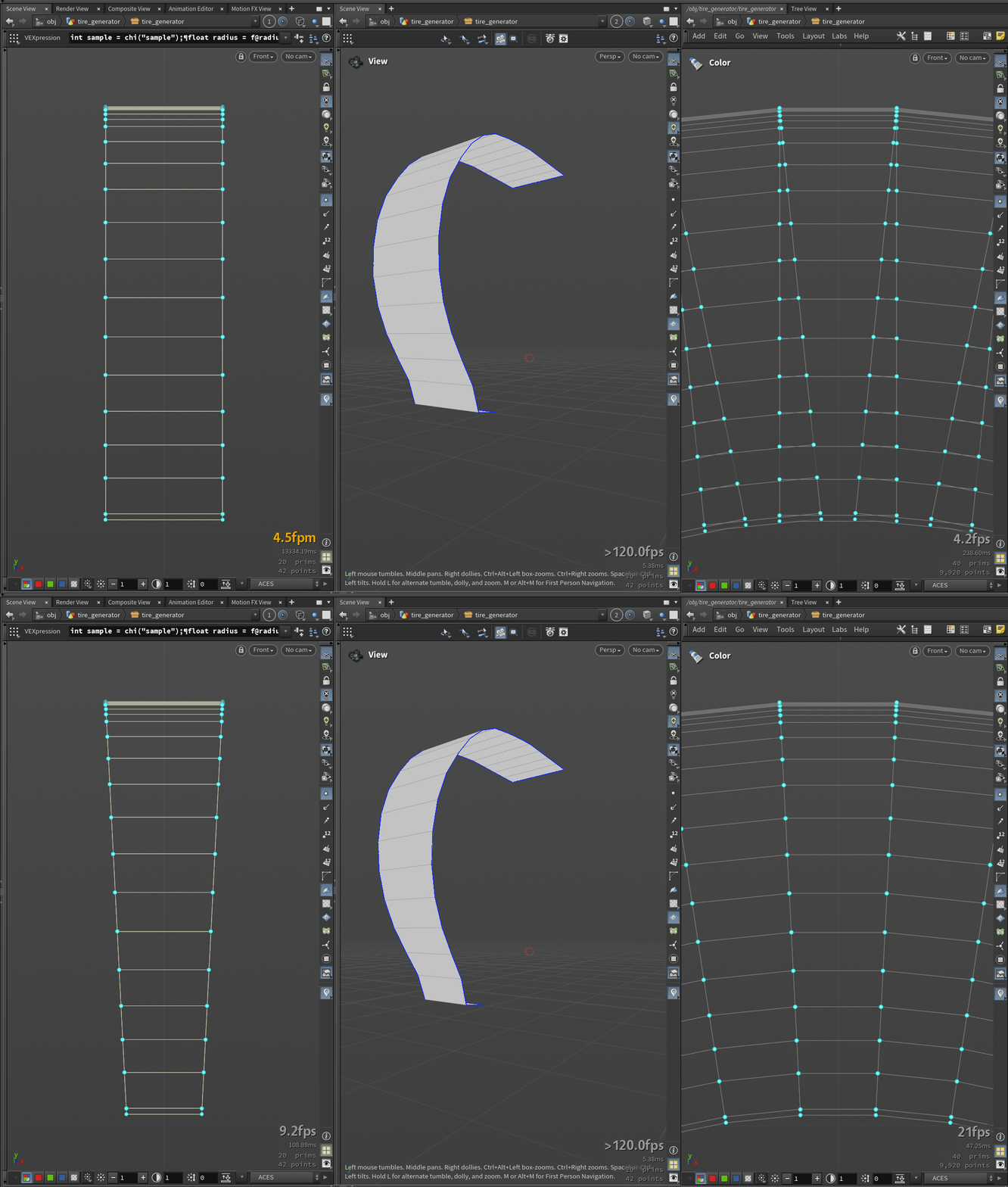
Once the tire profile is defined, the tread pattern is tiled. The minimum division for tread sections is set to 32 to ensure proper meshing. The tile itself is represented by a curve spanning from the outer circle to the inner circle of the tire.
To avoid point overlaps or misalignments along the tile length, each section is adjusted by calculating the angle θ for every spline section point. These corrections ensure a seamless, closed-loop cylinder without manual vertex tweaking.
| CONSTRAINT | SOLUTION |
|---|---|
| Minimum tread divisions | 32 — ensures clean polygon topology for subdivision |
| Tile representation | Curve from outer radius to inner radius — single repeating unit |
| Point alignment | Per-point θ correction — prevents overlap at tiling seams |
| Loop closure | Seamless closed cylinder — no manual vertex correction required |
04 Preparing for Extrusion
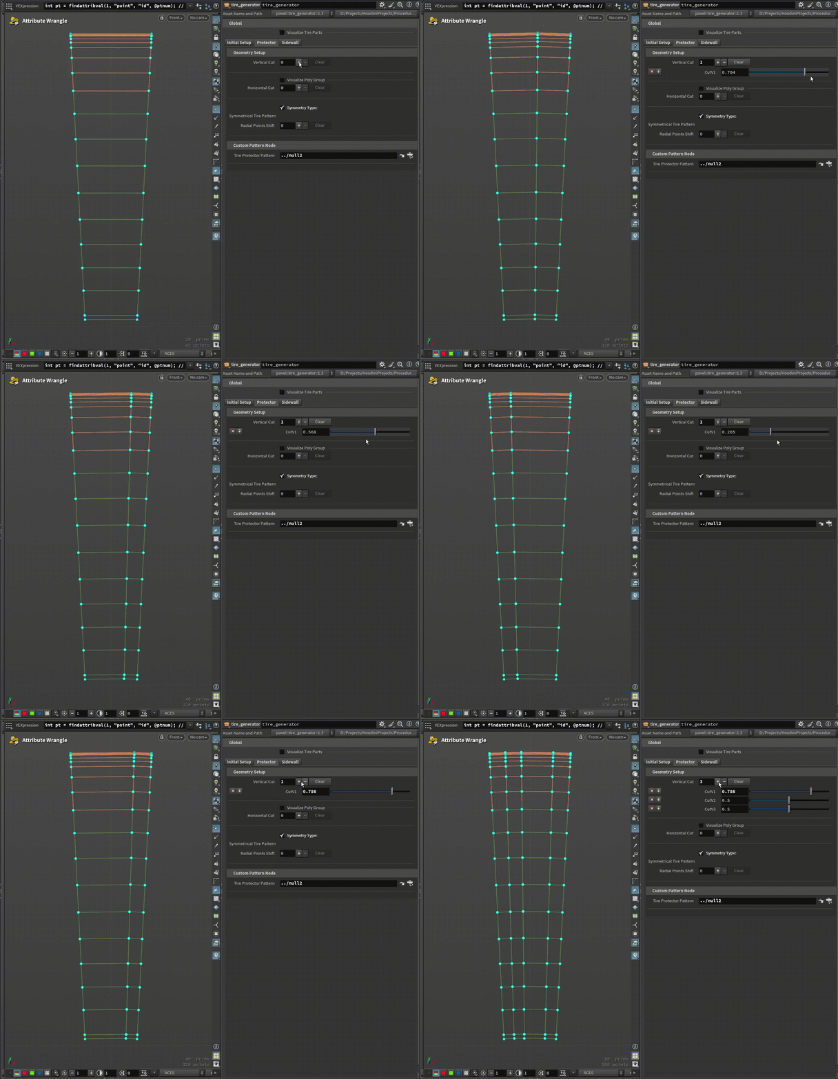
After generating the base tire shape, the geometry requires vertical and horizontal division for controlled extrusion. Standard Houdini tools proved inadequate here due to variations in polygon sizes and orientations — which led to the development of a custom subdivision tool.
This custom approach ensures uniform splitting by:
- Calculating edge weights and iteratively dividing groups
- Maintaining consistent polygon edge lengths across the topology
- Preserving circular radii to prevent geometric distortion during processing
05 Radial Polygon Displacement
For final tread height and shape, a dedicated radial displacement tool is used. It supports grouping of edge loops for both symmetrical and asymmetrical tread patterns. Soft selection ensures smooth transitions between displaced areas — providing high precision without hard polygon breaks at pattern boundaries.
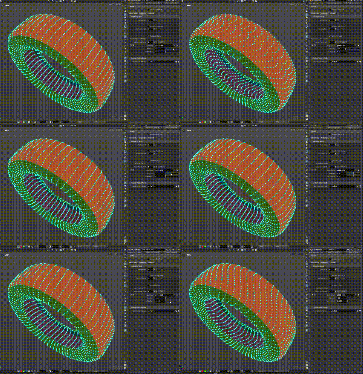
Asymmetrical tread designs — where inner and outer pattern depth differ — are handled by separate group assignments. Each group can receive independent displacement values while the underlying parametric logic keeps the result seamless across the full circumference.
06 UV Mapping Strategy
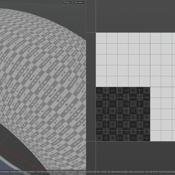
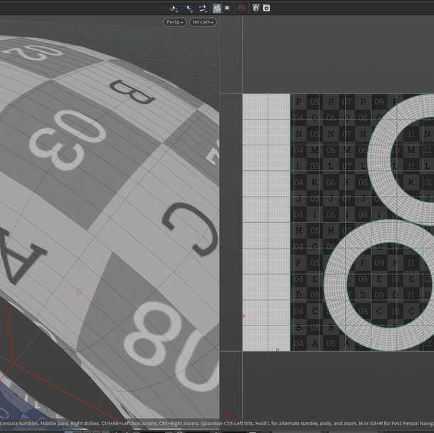
To support both complex tread patterns and sidewall branding, a dual UV mapping approach is employed:
| UV TYPE | COVERAGE | PURPOSE |
|---|---|---|
| Pattern-Based UVs | Tread + Sidewall quadrants | Dedicated mapping per surface area — essential for high-fidelity texturing and baking |
| Cylindrical UVs | Full circumference wrap | Seamless wrapping along the circular profile — minimises seams in game engines |
07 Sidewall Markings & SVG Export
To allow detailed sidewall customisation, I built an SVG export tool that converts geometry into splines and generates editable vector tiles. These can be edited in external software (Illustrator, Inkscape) and re-applied to the tire model.
The utility extends beyond tire branding — it functions as a general-purpose geometry-to-vector converter, reusable for any hard-surface asset requiring vector-based surface markings.
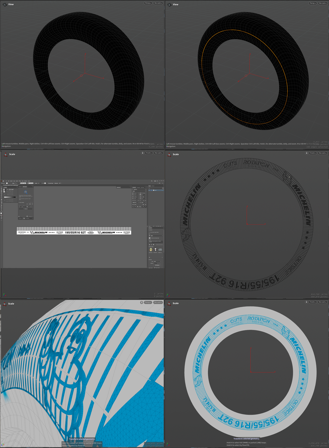
The core Python logic handles coordinate space transformation and SVG path generation:
# Define SVG dimensions — maintain aspect ratio from bounding box
width = maxsize if size.x() > size.y() else maxsize * size.x() / size.y()
height = maxsize * size.y() / size.x() if size.x() > size.y() else maxsize
# Transform: Houdini world space → SVG pixel space
# Y is flipped: SVG origin top-left, Houdini origin bottom-left
def transform_points(points):
return [hou.Vector2(
(p.x() - minv.x()) / size.x() * width,
(1.0 - (p.y() - minv.y()) / size.y()) * height
) for p in points]
# Write SVG — one per polygon primitive
with open(filename, 'w') as fp:
fp.write('') 08 Tread Pattern Creation
The tread pattern workflow balances creative freedom with procedural stability. Artists use standard modelling operations — extrusion, deletion, displacement — while the system handles the complex backend math automatically.
| AUTOMATED CONSTRAINT | WHAT IT PREVENTS |
|---|---|
| Seamless tiling | Pattern loop artifacts at circumference seam |
| Height adjustment | Non-uniform extrusion depth across different tire sizes |
| Surface alignment | Pattern lifting off the curved surface — eliminates manual vertex snapping |
By abstracting the technical work — math, snapping, looping — the artist focuses purely on tread design. The procedural system guarantees that any tread pattern will tile correctly, sit flush on the surface, and scale consistently regardless of the target tire specification.
-
[01]
SPEC — Tire and Rim Standards: Nomenclature and Markings. European Tire and Rim Technical Organisation.
etrto.org — Tire Standards Manual - [02]
- [03]
- [04]