01 Overview
This chapter covers a procedural environment creation workflow in Houdini for real-time production pipelines. It walks through building a procedural environment and optimizing its assets for game development, with the focus on modeling, texturing, and preparing assets efficiently while keeping performance suitable for a game engine such as Unity.
Implementation context: Houdini for terrain, road, remeshing, UVs, and baking; Unity for the splat map and wrapped tile atlas shader.
02 Project scope
The goal is to model and texture the provided assets: a modular building, and a terrain with a road. Each asset has a specific low texel density, polygon count, and material usage. The final deliverables are:
- a splat map mask for the terrain;
- a Wrapped Tile Atlas shader that uses a single texture, with the possibility of breaking the tiling of the ground;
- a procedural modular building that keeps the performance impact low.
This chapter covers the terrain and the road. The modular building is planned for the next chapter.
03 Heightfield and road alignment
Heightfield generation
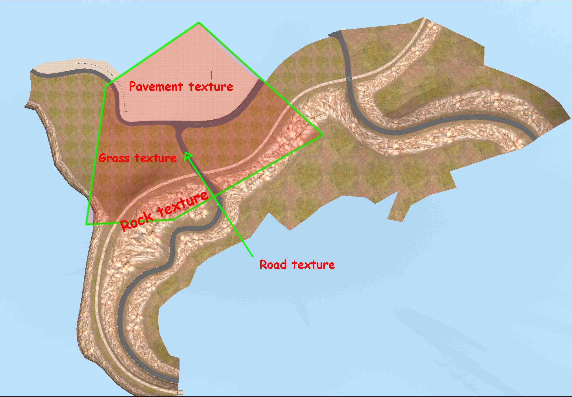
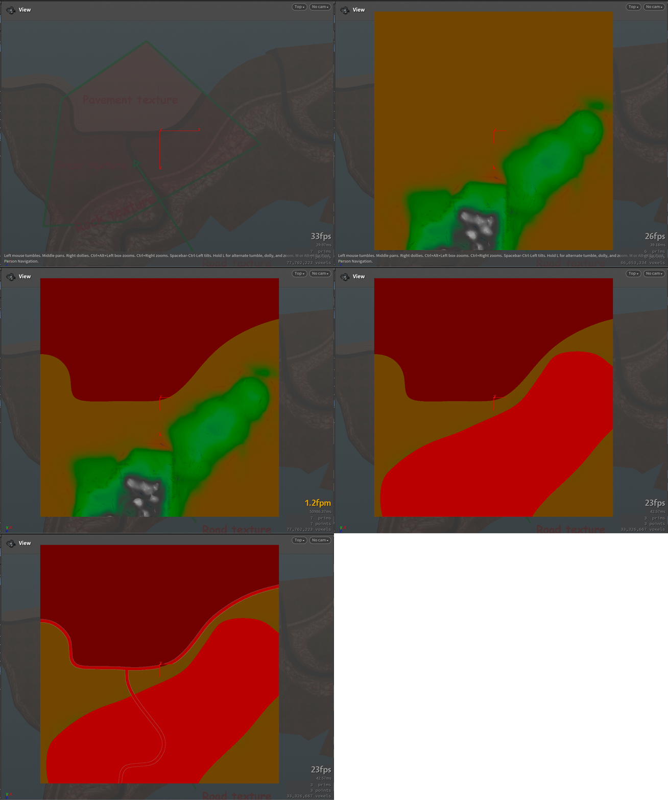
Generate the terrain and draw the road using curves and the Labs Road Generator, Expand2D, Sweep, or a custom solution. At this stage it is crucial to store masks of the zones and terrain types, because they help with remeshing and with the wrapped tile atlas later.
Road alignment
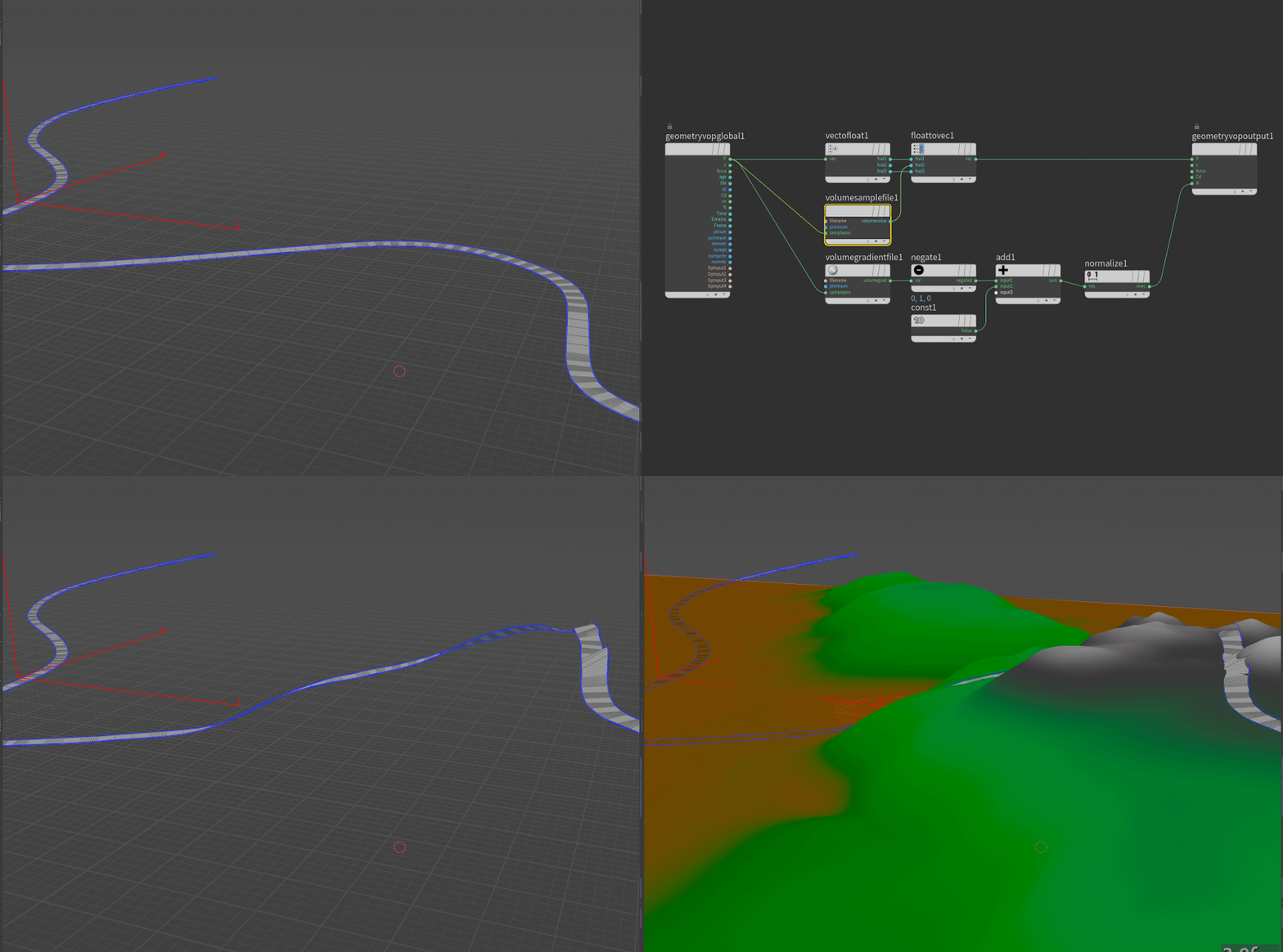
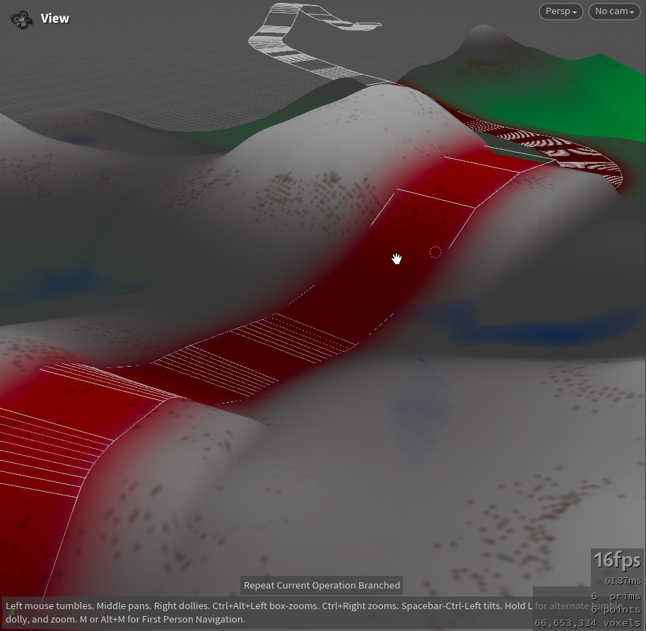
The road passes through mountainous terrain, and the generated mountain surface (the heightfield) is a high-density volume with unevenness. Projecting a low-poly road mesh onto this volume can distort the geometry and add unnecessary slopes to the road surface. Aligning the road takes several steps.
Step 1 — project the points onto the volume
Step 2 — define and group edges by the maximum Y position in the row
These VEX helpers group edge loops, find the next edge from the current primitive, and collect the primitives connected by an edge. They are shown as they were written for this setup.
// Main function for grouping edge loops
void GroupEdgeLoops(int input, string edgegroup, groupname) {
    if (edgegroup == "") {
        setedgegroup(geoself(), groupname, 0, 0, 0);  // If the edge group is empty, clear the group
        return;
    }

    int edges[] = expandedgegroup(input, edgegroup);  // Expand the edge group into an array of edges
    if (len(edges) == 0) {
        setedgegroup(geoself(), groupname, 0, 0, 0);  // If no edges are found, clear the group
        return;
    }

    int count = int(0.5 * len(edges));  // Calculate the number of edges
    for (int i = 0; i < count; ++i) {
        int edgepts[] = sort(array(edges[2*i], edges[1+2*i]));  // Sort the edge points
        int index0 = find(loopedgepts, edgepts[0]);  // Find the index of the first edge point in the loop
        int index1 = find(loopedgepts, edgepts[1]);  // Find the index of the second edge point in the loop
        if (!edgefound) {
            // The logic for processing edge loops continues here
        }
    }
}
// Function to get the next edge based on the current primitive and edge points
function int[] GetNextEdge(int input, int edgept0, int edgept1, int currentprim) {
int primpts[];
int count = primvertexcount(input, currentprim); // Get the number of vertices in the primitive
for (int f = 0; f < count; ++f) {
int vertIndex = vertexindex(input, currentprim, f); // Get the vertex index
int pointIndex = vertexpoint(input, vertIndex); // Get the point index
if (pointIndex != edgept0 && pointIndex != edgept1)
append(primpts, pointIndex); // Add the point index if it's not part of the edge
}
int pt0 = min(primpts[0], primpts[1]); // Get the minimum point index
int pt1 = max(primpts[0], primpts[1]); // Get the maximum point index
return array(pt0, pt1); // Return the array of next edge points
}// Function to get all primitives connected by a given edge
function int[] GetPrimsFromEdge(int input, int pt0, int pt1) {
int prims[];
int hedge = pointedge(input, pt0, pt1); // Get half-edge from the given points
if (hedge != -1) {
int count = hedge_equivcount(input, hedge); // Get the equivalent count of the half-edge
for (int i = 0; i < count; ++i) {
int pr = hedge_prim(input, hedge); // Get the primitive from the half-edge
if (pr != -1) {
append(prims, pr); // Add the primitive to the array
hedge = hedge_nextequiv(input, hedge); // Move to the next equivalent half-edge
}
}
}
return prims; // Return the array of primitives
}Step 3 — copy the highest point's Y position to the lowest points in the row
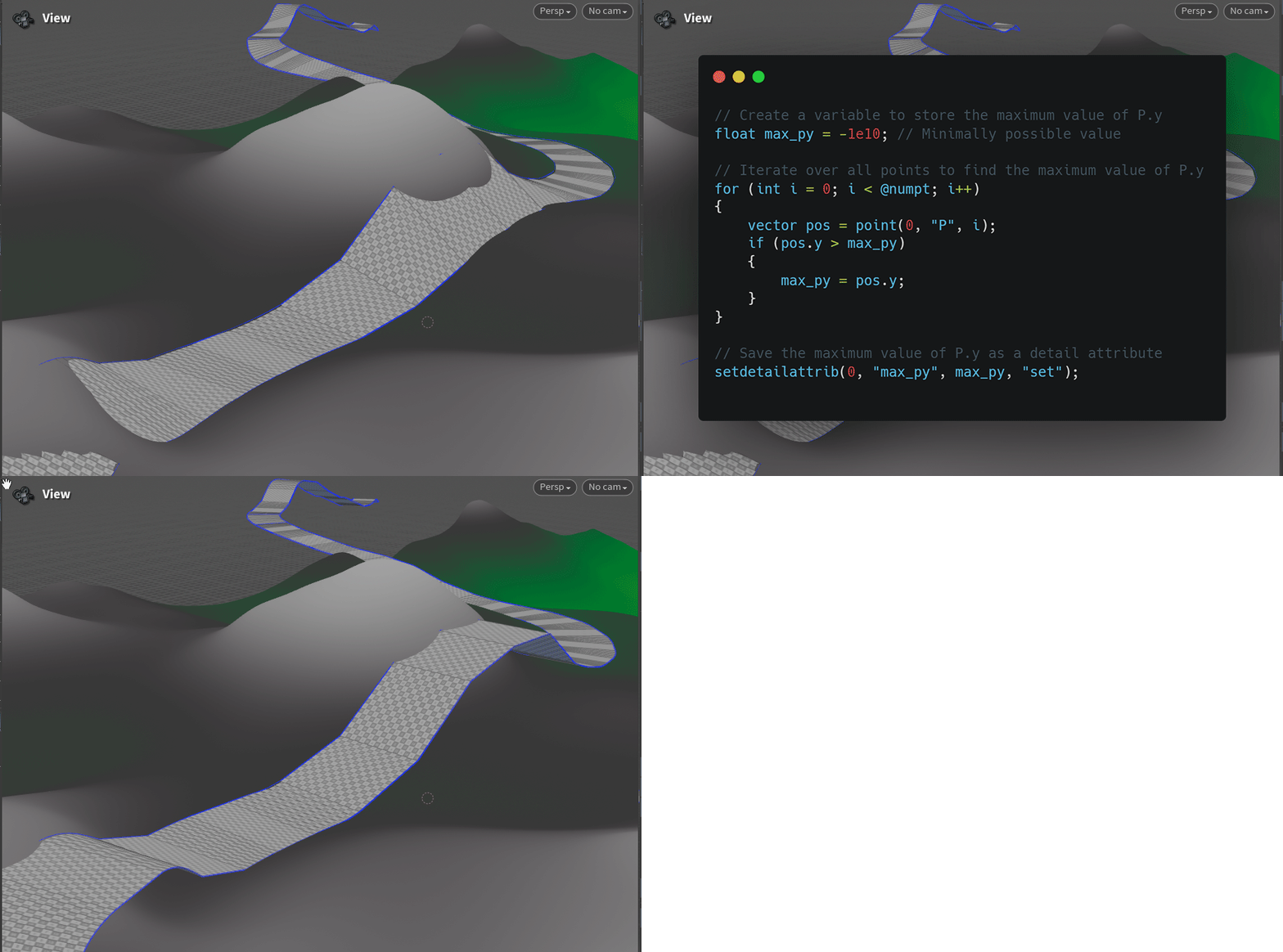
Step 4 — adjust the terrain heightfield to the road
The heightfield is adjusted to the newly repositioned road. Since the road is already aligned by the previous steps, the transitions and slopes along the road path have to be smoothed to avoid harsh geometry changes.
04 Dense mesh and terrain zones
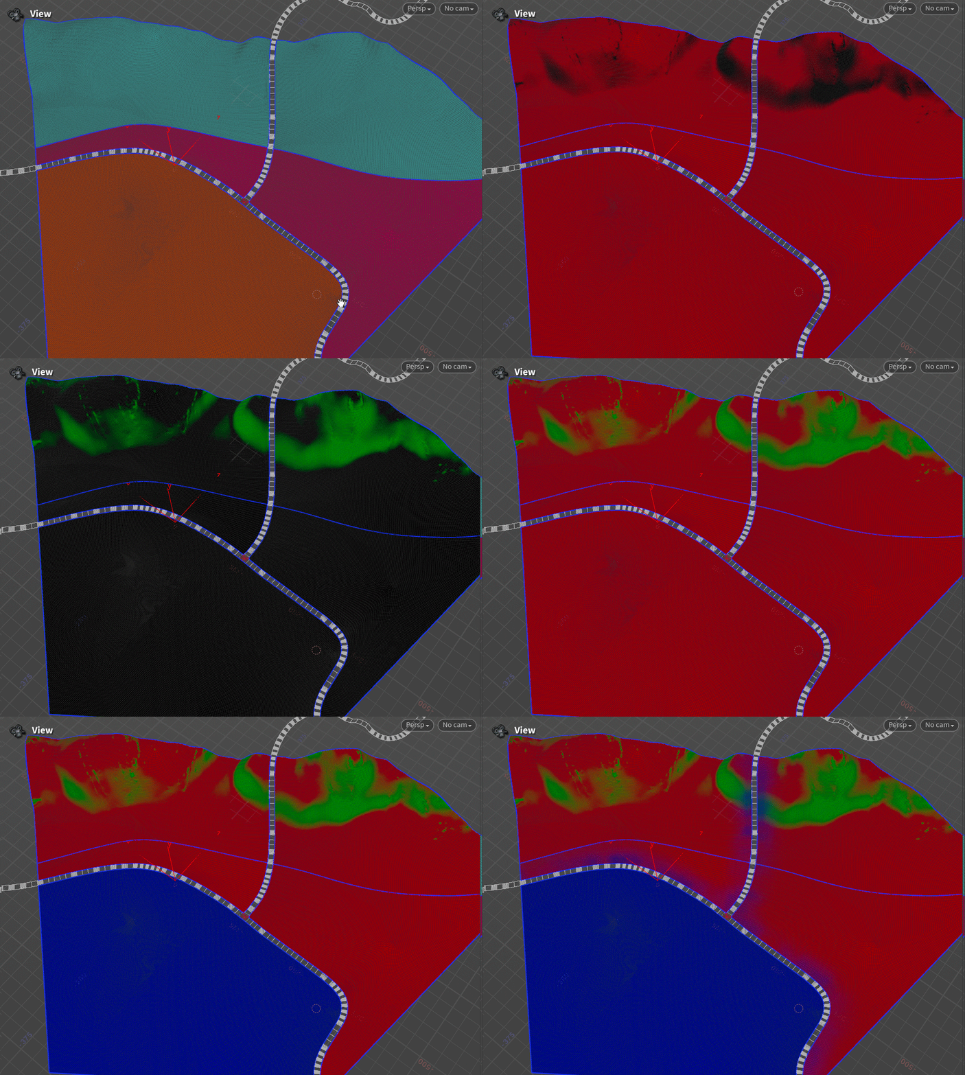
Convert the heightfield and store the layers
Once the terrain layers are stored in a primitive attribute and the road alignment and smoothing are complete, the heightfield volume can be converted into a dense mesh. This step matters most when texture baking is needed for normal maps, ambient occlusion (AO), or curvature maps.
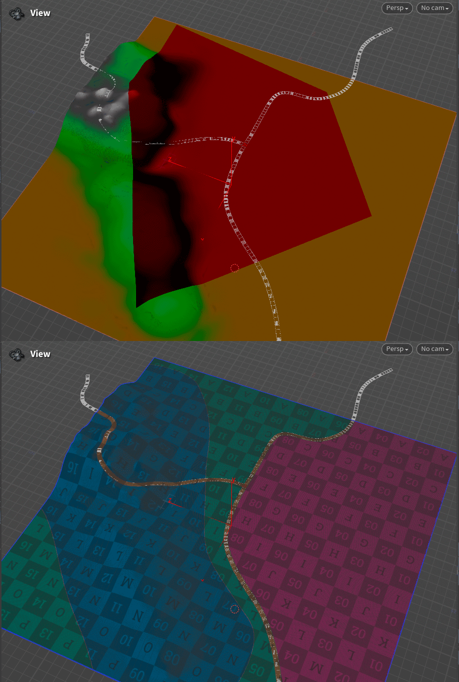
Assign the splat map zones
Different colored zones are assigned to the terrain for the splat map mask baking. They mark areas with different terrain types (for example roads, grass, dirt) that are later used for texture blending in a game engine or rendering software.
05 Remeshing and welding to the road
Remeshing is divided into several substeps to reduce the polycount without losing essential geometry, especially along mesh boundaries.
Reduce the polycount per zone
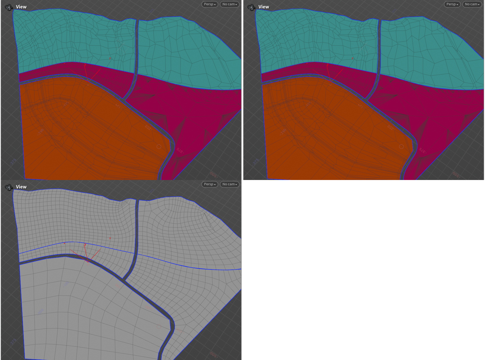
The first substep reduces the polycount individually for each terrain zone. Each zone can have a different surface area, so uniform remesh settings across the entire mesh can be interpreted badly and lose crucial geometry, particularly at the edges.
Weld the terrain to the road
This was the most interesting and challenging part of the process. The goal was to weld all terrain points to the road seamlessly while the road mesh itself remained unchanged.
First, all borders of each terrain zone are grouped to prepare for the welding and division process. This is what lets different terrain areas connect seamlessly while keeping their distinct characteristics.
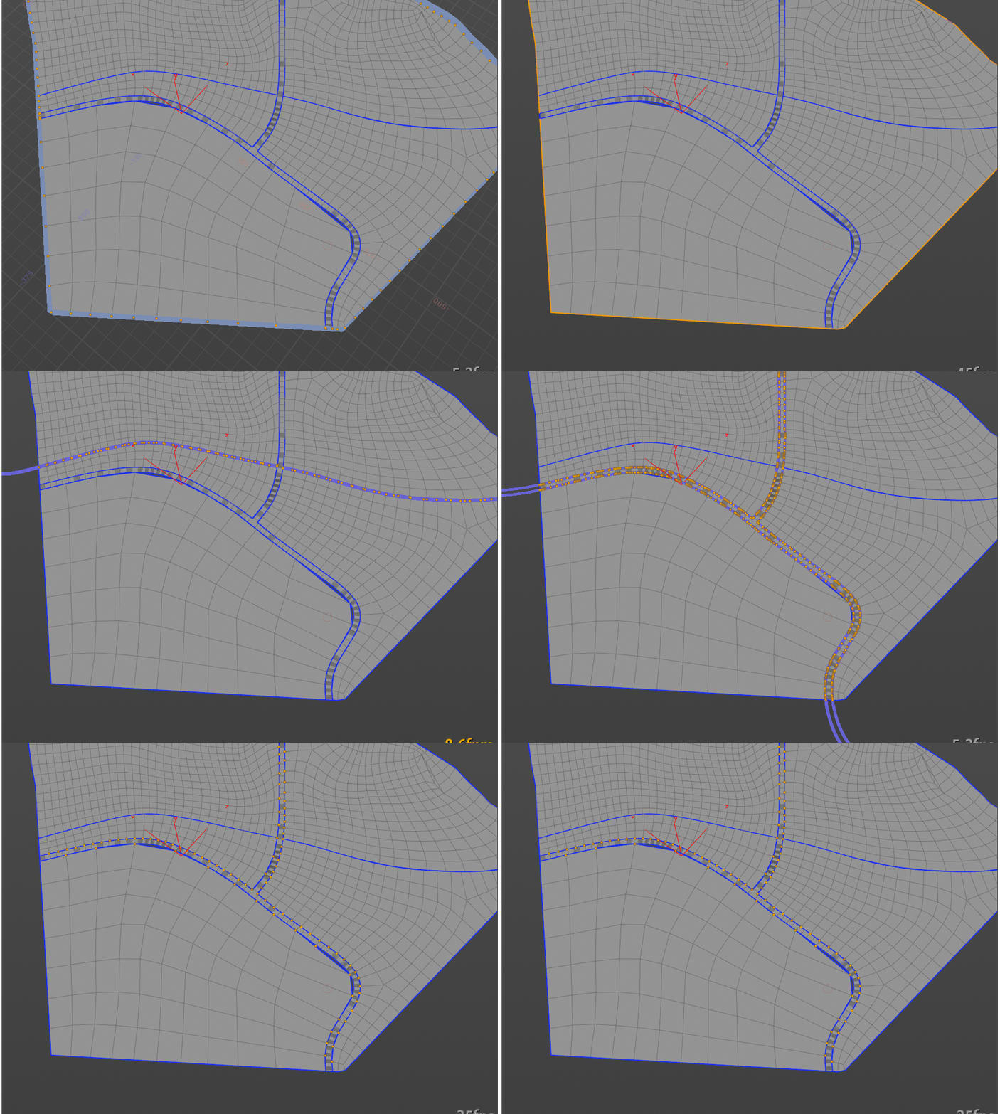
Combining meshes of different polycounts is designed to be fully procedural, so terrain zones and the road blend automatically without changing the road geometry.
How it works:
- Points that touch the road at the terrain zone borders are added to a group, and the group is promoted to edges and primitives.
- The outer contour is subtracted from these groups, which determines which points need to be welded with the road mesh points later.
- Knowing which points and edges form the boundary between the terrain and the road mesh, a central point is added to each of these "contact edges", and a bisector is drawn from that vertex, which triangulates the polygon.
- The new point is added to a separate group and later welded with the nearest edge point of the road mesh, based on distance.
- The whole process runs inside a For-Each Loop with Feedback that iterates until no new groups are formed.
Houdini is well suited to problems like this: even the iteration count can be derived by checking the mesh for non-connected polygons.
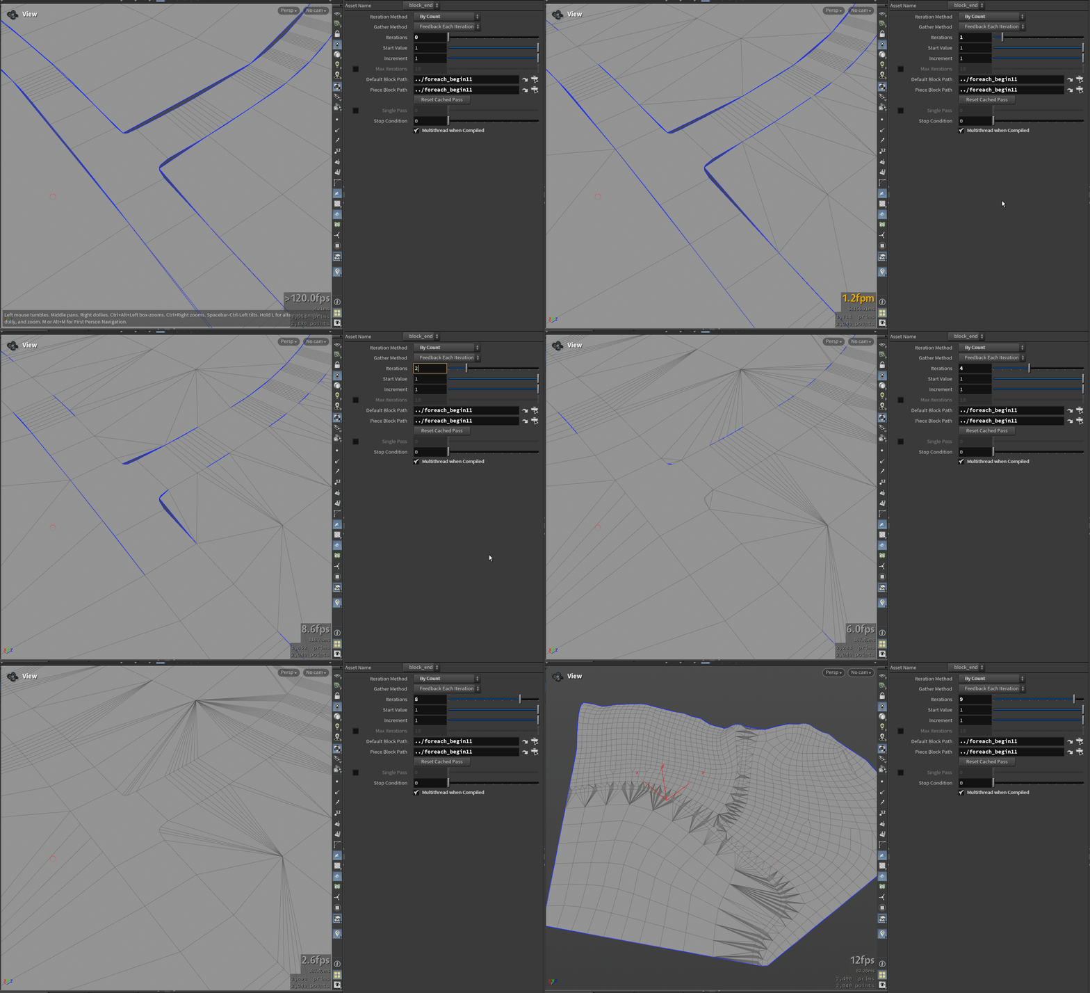
Result of this stage: the terrain and road form a single game-ready mesh at 3111 triangles in total, and the road mesh is unchanged.
06 UVs, splat map, and atlas textures
Auto UVs
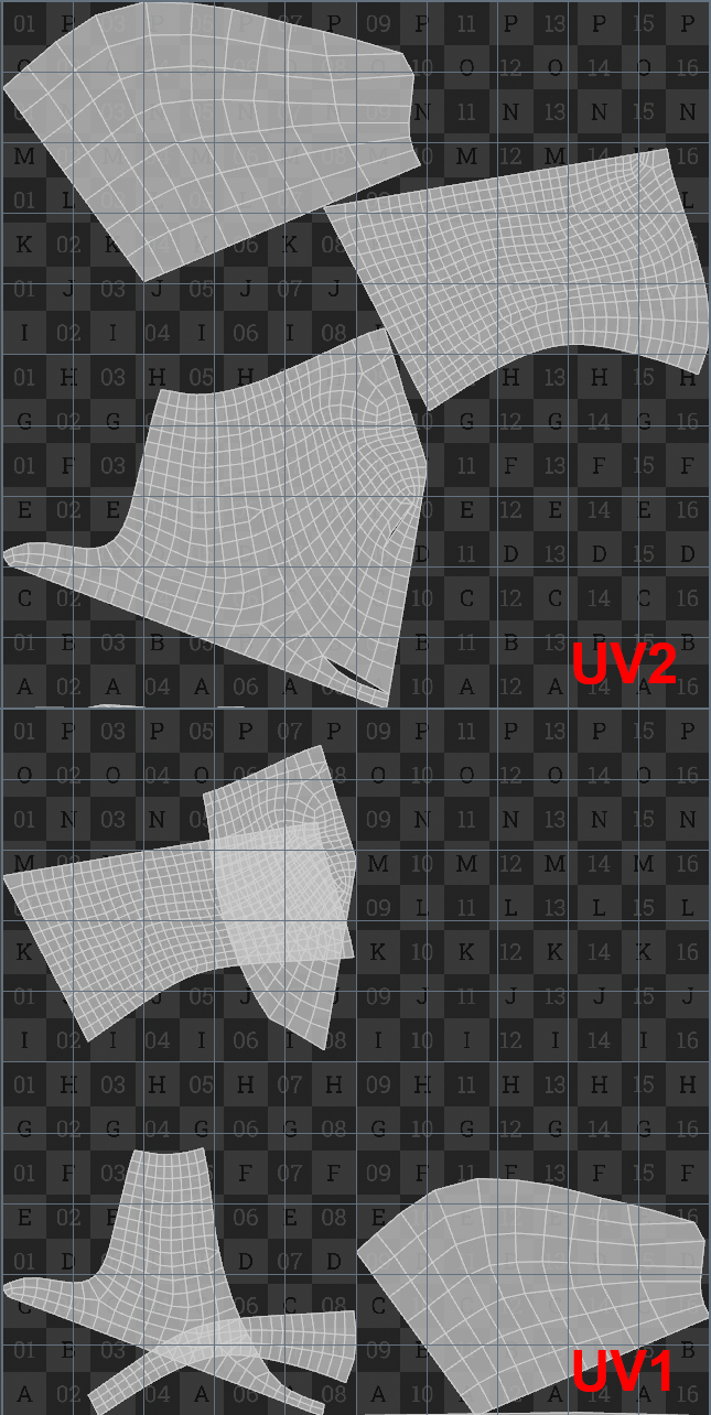
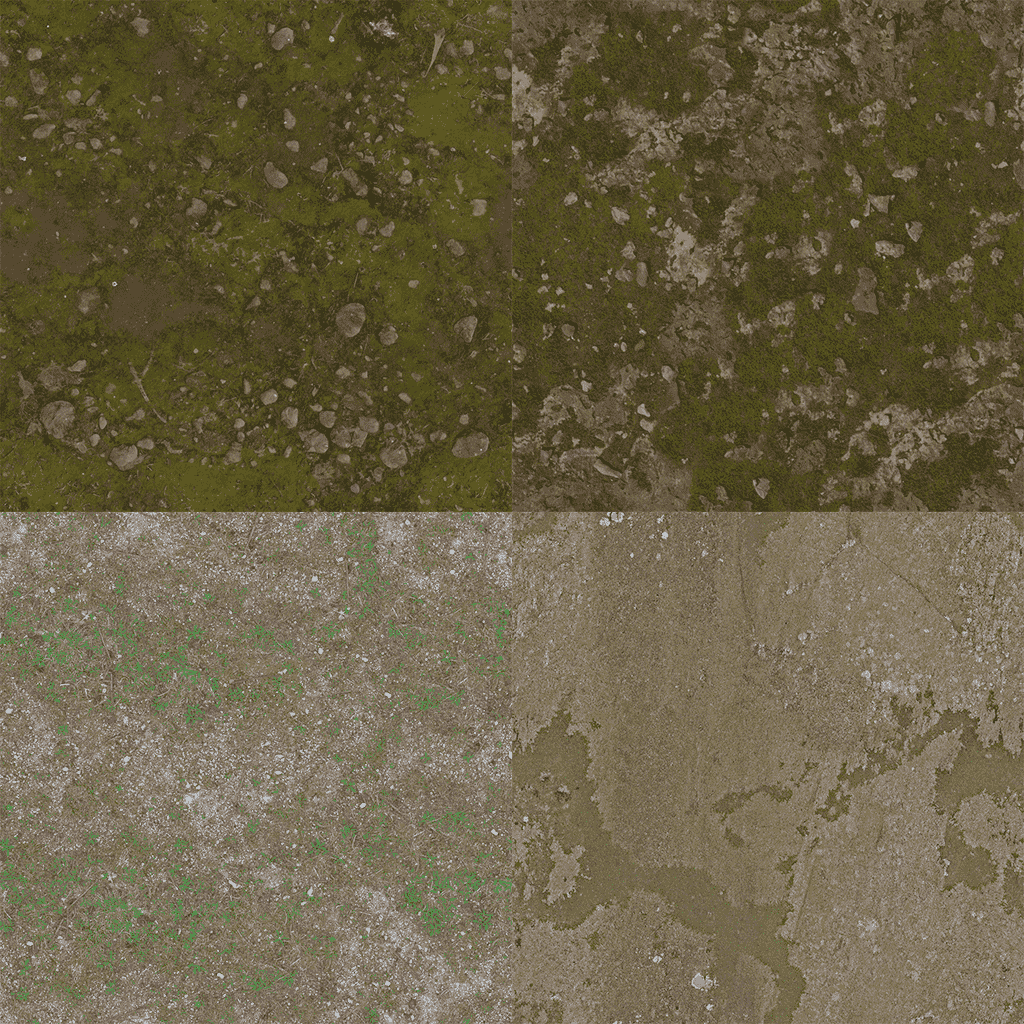
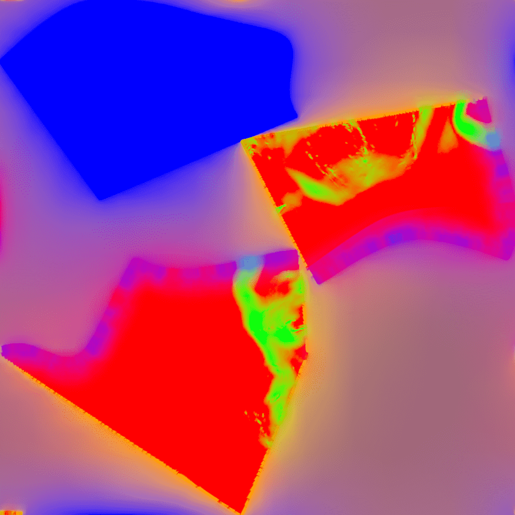
The mesh gets two UV channels. The first UV is for the Wrapped Tile Atlas: depending on the number of terrain types, the UV can be divided into sections. Here there are three sections, so each tile is equal to x0.5. The second UV channel is used for splat map masking and light baking.
Preparing the atlases and other textures
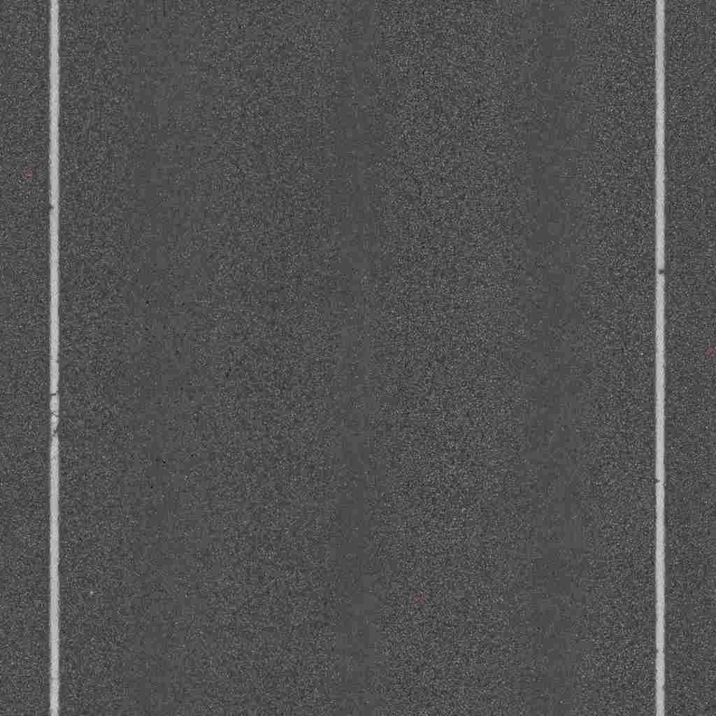
The color information of the splat map is baked into a texture using the second UV. An atlas is also created with two different grass textures and two different rocky textures. This kind of texture atlas reduces draw calls and breaks the repetitiveness of the terrain texture.
07 Shader: splat map and wrapped tile atlas
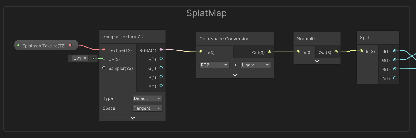
The splat map setup is straightforward: splitting the color channels makes it easy to mask the terrain zones.
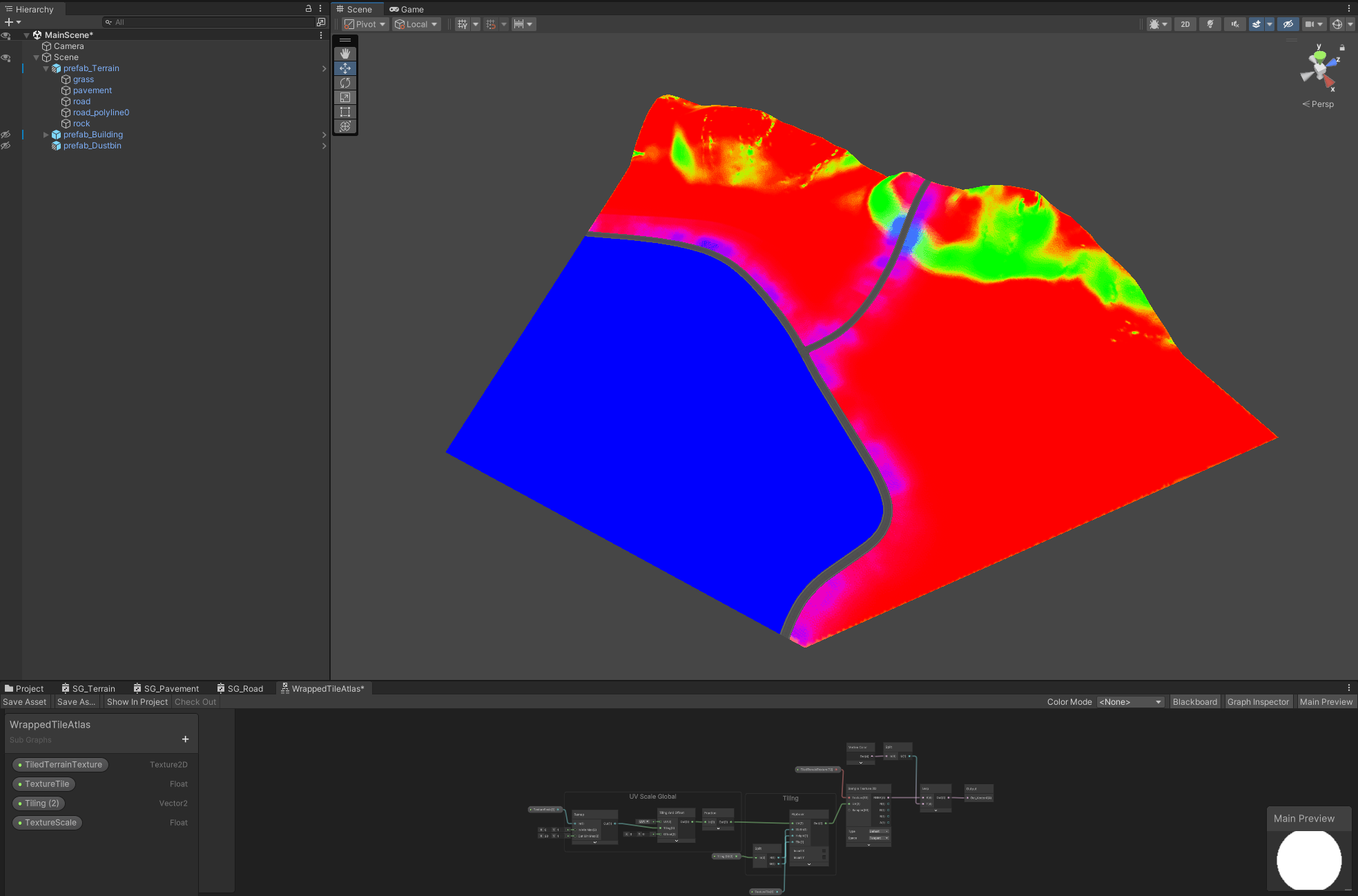
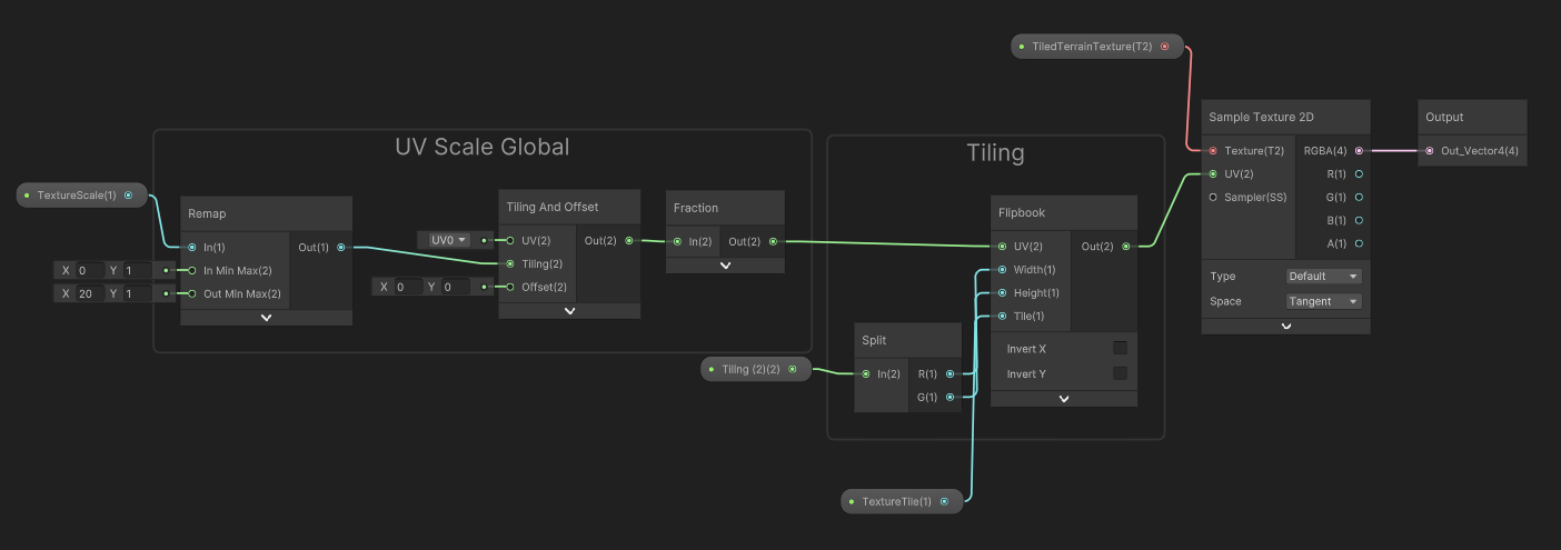
The wrapped tile subgraph
The terrain texture atlas is remapped, which helps scale it on the geometry, and it is fed into the tiling node using the first UV. The next step is the Fraction function, which returns the fractional part of its input. For example, if the input is 3.75, Fraction returns 0.75, which means it works within the borders of one UV tile, here x0.5. This is useful for repeating or cyclical effects, and here it keeps the sampling inside the tile UV that is defined in the Flipbook node. The value is a Vector2 Tiling, which is then connected to the input of the texture atlas.
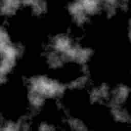
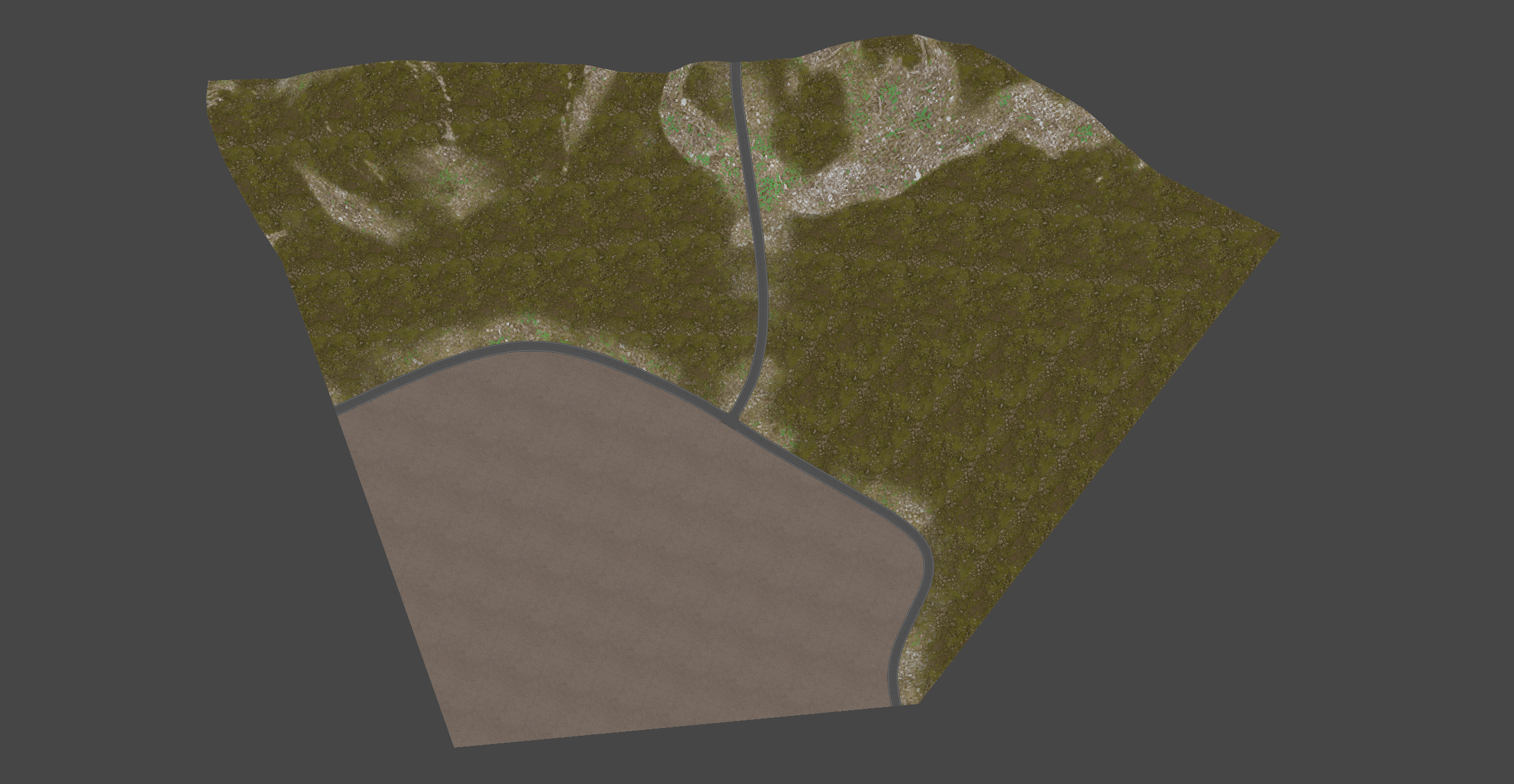
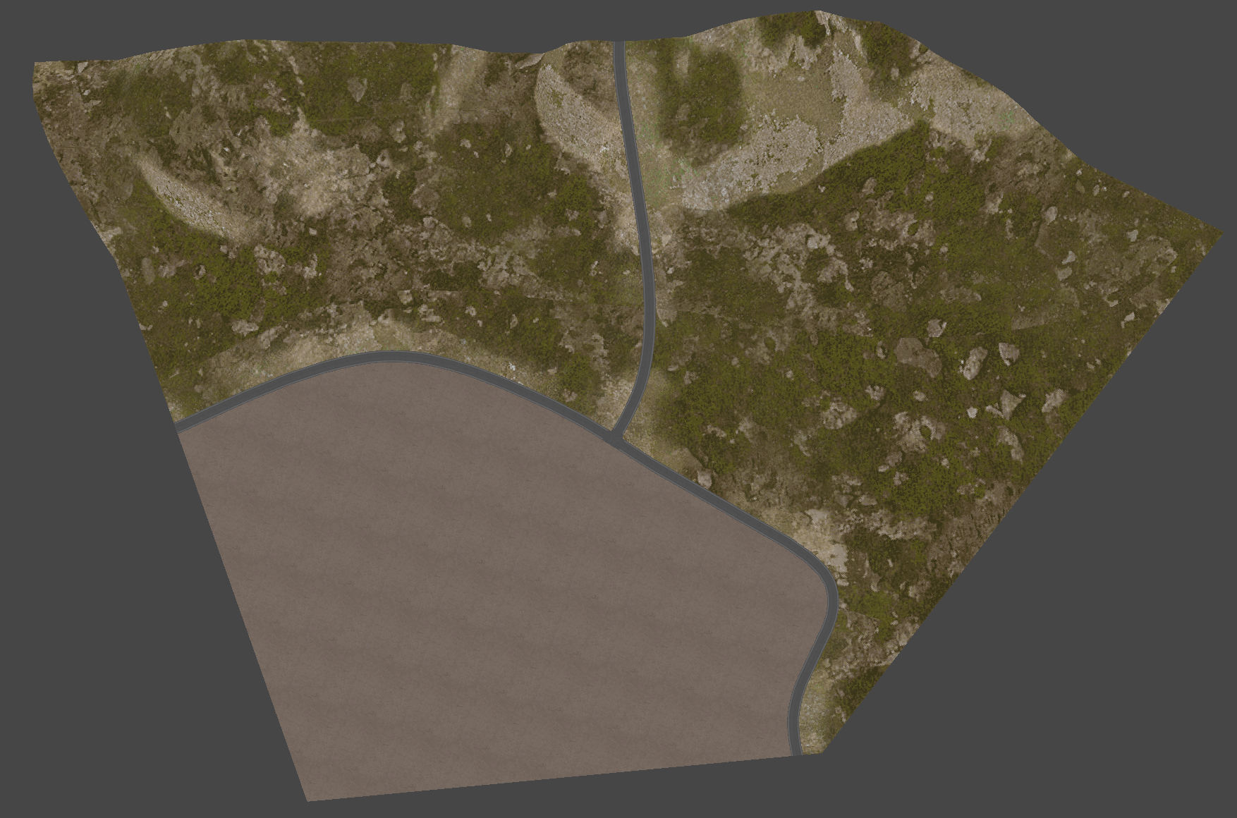
With this setup a single texture can be scaled and offset, and all of it stays within the bounds of the tile UV and that single texture. It can also be mixed with the neighboring texture using a noise mask multiplier, which helps break the repetitiveness of the terrain.
08 Result and next chapter
The terrain and road are a single low-poly mesh with two UV channels, a baked splat map, and a texture atlas that breaks repetition with a single shader setup. In the next chapter, I'll demonstrate how to create a procedural, optimized modular building.
Like this post? ( ´◔ ω◔`) ノシ
Support: Buy Me a Coffee | Patreon | GitHub | Gumroad | YouTube